Multiplexer

a multi-channel, multi-channel technology, applied in the direction of impedence networks, electrical equipment, etc., can solve the problems of suppressing multiple unnecessary signals, difficult for a small-sized cancel circuit, etc., to improve the isolation characteristics of the filter 10 or reduce or prevent the effect of reducing the attenuation characteristics of the filter 10

Active Publication Date: 2020-07-28
MURATA MFG CO LTD
View PDF5 Cites 2 Cited by
  • Summary
  • Abstract
  • Description
  • Claims
  • Application Information

AI Technical Summary

Benefits of technology

[0064]In the multiplexer 1A according to the present example, if the filters 10 and 20 are ladder elastic wave filter circuits, the phase will not vary in a complex manner in the attenuation bands of the filters 10 and 20. Accordingly, signals having an inverse phase with respect to the unnecessary signals flowing in the filter 10 and the filter 20 are able to easily be provided by the cancel circuits 30A and 40A, which are defined by longitudinally-coupled resonators. As such, the advantageous effects of improving the isolation characteristics of the filter 10 and the filter 20 is even more pronounced.
[0065]In the multiplexer 1A according to the present example, the capacitance element 50 is connected between the transmission-side input / output terminal 110 and the cancel circuit 30A. Accordingly, the impedance when viewing the cancel circuit 30A from the input / output terminal 110 is able to be adjusted. The multiplexer 1A according to the present example handles the above-described impedance as an impedance in the pass band of the filter 10 (the first frequency band), for example. In other words, the impedance in the first frequency band, when viewing the cancel circuit 30A from the input / output terminal 110 side, is able to be adjusted. This makes it possible to reduce or prevent situations in which a signal in the first frequency band, input from the input / output terminal 110, does not travel toward the filter 10 and, instead, leaks to the cancel circuit 30A.
[0066]Note that the frequency at which the cancel circuit 30A has a minimum insertion loss may be located in at least one of the first frequency band and the second frequency band. This improves the attenuation characteristics of the filter 10 or 20, which improves the isolation characteristics of the filter 10 and the filter 20.
[0068]FIG. 3 is a graph comparing the isolation characteristics of multiplexers according to the

Problems solved by technology

In other words, it is difficult for a small-sized cancel circuit, such as a single-stage longitudinally-coupled elastic wave resonator, to suppress multiple unnecessary signals, such as unnecessary signals in two or more discrete frequency ranges or multiple unnecessary signals having different signal strengths.

Method used


Image

  • Multiplexer
  • Multiplexer
  • Multiplexer

Examples


Embodiment Construction

[0034]Hereinafter, preferred embodiments of the present invention will be described in detail with reference to examples and the accompanying drawings. Note that the preferred embodiments described hereinafter provide comprehensive or specific examples. The numerical values, shapes, materials, elements, arrangements of elements, connection structures, and other elements and features described in the following preferred embodiments are merely examples, and are not intended to limit the scope of the present invention. Of the elements described in the following preferred embodiments, elements not recited in the independent claims are described as optional elements. Furthermore, the sizes or size ratios of the elements illustrated in the drawings are not necessarily exact.

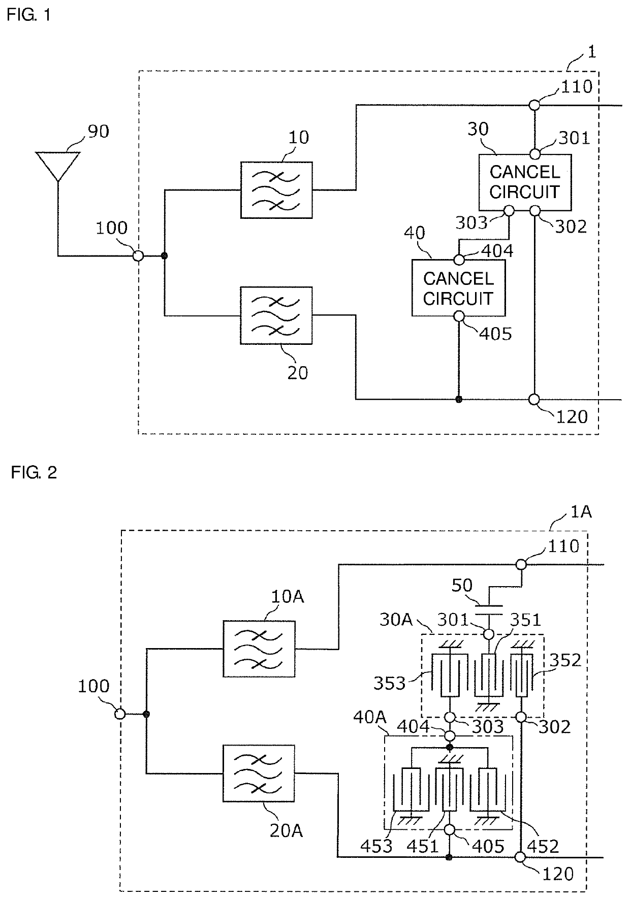
[0035]FIG. 1 is a circuit configuration diagram illustrating a multiplexer 1 and peripheral circuitry thereof, according to a preferred embodiment of the present invention. FIG. 1 illustrates the multiplexer 1 and an a...


PUM


Abstract

A multiplexer includes a first filter connected to a common terminal and a first input / output terminal, a second filter connected to the common terminal and a second input / output terminal, a first cancel circuit including a first terminal, a second terminal acoustically connected to the first terminal, and a third terminal acoustically connected to the first terminal, and a second cancel circuit including a fourth terminal, and a fifth terminal acoustically connected to the fourth terminal. The first terminal is connected to the first input / output terminal. The second terminal is connected to the second input / output terminal. The fourth terminal is connected to the third terminal. The fifth terminal is connected to the second input / output terminal. The first and second cancel circuits generate signals that cancel out unnecessary signals in a prescribed frequency band propagating between the first and second input / output terminals.

Description

CROSS REFERENCE TO RELATED APPLICATIONS[0001]This application claims the benefit of priority to Japanese Patent Application No. 2018-058117 filed on Mar. 26, 2018. The entire contents of this application are hereby incorporated herein by reference.BACKGROUND OF THE INVENTION1. Field of the Invention[0002]The present invention relates to a multiplexer including a filter circuit.2. Description of the Related Art[0003]In order to handle a trend toward multiple bands, recent cellular phones are provided with multiplexers, which are disposed immediately below the antennas and include multiple filters corresponding to different pass bands.[0004]Japanese Unexamined Patent Application Publication No. 2013-118611 discloses a cancel circuit configuration in which the circuit is disposed between the input terminal of a transmission filter and the output terminal of a reception filter defining a multiplexer, with the circuit generating a signal component having a phase inverse with respect to a...

Claims


Application Information

Patent Timeline
Patent Type & Authority Patents(United States)
IPC IPC(8): H03H9/70H03H9/54H03H9/13H03H9/00
CPCH03H9/13H03H9/706H03H9/54H03H9/0014H03H9/725H03H9/42
Inventor ARAKI, MASATO
Owner MURATA MFG CO LTD
Why Eureka
Try Eureka