Method of controlling loudspeaker diaphragm excursion

a diaphragm and loudspeaker technology, applied in the direction of transducer protection circuits, electrical transducers, transducer circuits, etc., can solve the problems of large diaphragm excursions, various kinds of irreversible mechanical damage, and the diaphragm excursion requirement can exceed the safe operating range of the loudspeaker, so as to reduce the amount of audible artefacts

Active Publication Date: 2020-07-28
PURIFI APS
View PDF6 Cites 0 Cited by
  • Summary
  • Abstract
  • Description
  • Claims
  • Application Information

AI Technical Summary

Benefits of technology

[0016]The selective attenuation of the low-frequency components of the second audio signal is preferably controlled not to be overly conservative so that the available excursion headroom of the controlled loudspeaker is utilized fully without being exceeded. This feature prevents that the maximum sound pressure capability of the connected or controller loudspeaker is not unduly restricted.
[0024]The addition of the predetermined time delay to the second audio signal may be advantageous to properly align a time delay through an audio signal path of the diaphragm excursion limiter to a time delay through a control path of the diaphragm excursion limiter as discussed in additional detail below with reference to the appended drawings.
[0026]comparing the excursion envelope to an excursion threshold representing a predetermined excursion value of the diaphragm, e.g. a maximum diaphragm excursion; and if, or when, the excursion envelope is smaller than the excursion threshold: maintain a substantially stationary response of the adjustable low-frequency suppressor. If the excursion envelope on the other hand is larger than, and possibly equal to, the excursion threshold, the second audio signal may be processed to selectively increase the attenuation of the low-frequency components of the audio signal with increasing magnitude of the excursion envelope following a certain predetermined relationship as discussed in additional detail below. This embodiment may lead to a substantially stationary frequency response of the adjustable low-frequency suppressor for audio signal levels below the excursion threshold which is helpful to eliminate or suppress unwanted amplitude modulation or “pumping” effects of the processed audio signal.
[0042]The adjustable high-pass filter may comprise a digital filter for example an IIR filter or FIR filter configured to filtering the second audio signal in the time-domain. An architecture of the digital filter may be chosen such that a momentary change of the cut-off frequency produces minimal momentary changes of the processed output signal of the digital filter thereby acting to minimize audible artefacts induced by the dynamic adjustment or change of the cut-off frequency. One embodiment of the digital filter comprises a state-space representation of a 2nd order LCR continuous-time high-pass filter. The filter inductance L and the filter capacitance C are both inversely proportional to the selected cut-off frequency. The states of the state-space filter may comprise digital integrators representing the capacitor voltage and inductor current such that a change of cut-off frequency appears only as multiplications at an input side of each of the digital integrators. Consequently, the outputs of the digital integrators will change relatively smoothly in response to an abrupt change of cut-off frequency.

Problems solved by technology

Consequently, reproduction of low frequency sound pressure requires large diaphragm excursions.
The resulting excursion requirement of the diaphragm can exceed the safe operating range of the loudspeaker under numerous circumstances—for example when the loudspeaker is driven by a powerful amplifier and operating at a high playback volume.
In the latter situation, the power amplifier may drive the diaphragm and voice coil assembly beyond its maximum excursion limit leading to various kinds of irreversible mechanical damage.

Method used


Image

  • Method of controlling loudspeaker diaphragm excursion
  • Method of controlling loudspeaker diaphragm excursion
  • Method of controlling loudspeaker diaphragm excursion

Examples


first embodiment

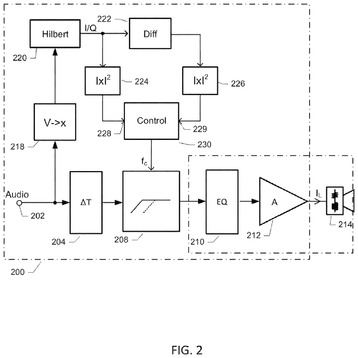
[0079]FIG. 2 shows a simplified schematic block diagram of a diaphragm excursion limiter 200 in accordance with the invention. The diaphragm excursion limiter 200 comprises an audio signal path extending between an audio input 202 and an audio output 216. The audio input 202 is configured for receipt of an incoming / input audio signal from various types of audio signal sources. The audio signal path comprises a cascade of interconnected processing functions or circuits between the audio input 202 and the audio output 216. The audio signal path comprises a cascade of interconnected processing functions such as a time delay function or circuit 204, an adjustable low-frequency suppressor 208, e.g. comprising an adjustable high-pass filter, an optional equalizer function or circuit 210 and a power or output amplifier 212. The output of the power amplifier forms the audio output 216 and may be connected to a loudspeaker 214 such as the above-discussed exemplary electrodynamic loudspeaker ...

embodiment 200

[0094]The audio signal path of the diaphragm excursion limiter 400 extends between an audio input 402 and an audio output 416. The audio signal path comprises a cascade of interconnected processing functions such as an optional equalizer function or circuit 410, an excursion estimator 418, a time delay function or circuit 404, an adjustable low-frequency suppressor 408, e.g. comprising an adjustable high-pass filter, an inverse excursion estimator 438 and a power or output amplifier 412. The excursion estimator 418 is configured for determining an excursion signal representing diaphragm excursion of the loudspeaker 414 based directly on the incoming audio signal at input 402 or an equalized audio signal supplied at the output of the equalizer function 410. The operation of the diaphragm excursion estimator 418 may be identical to the previously discussed diaphragm excursion estimator 218. However, in contrast to the previously discussed excursion limiter 200, the excursion signal is...


PUM


Abstract

The present invention relates in one aspect to a method of controlling or limiting diaphragm excursion of a loudspeaker. The method comprising steps of receiving a first audio signal and deriving an excursion signal representing diaphragm excursion of the electrodynamic loudspeaker from the first audio signal. The method additionally comprises deriving an excursion envelope from the excursion signal and applying a second audio signal, derived from the first audio signal, to an input of an adjustable low-frequency suppressor. The second audio signal is filtered by the adjustable low-frequency suppressor to selectively attenuate low-frequency components based on the excursion envelope to produce a processed audio signal with reduced low-frequency content.

Description

CROSS-REFERENCE TO RELATED APPLICATIONS[0001]This application is a national phase under 35 U.S.C. § 371 of PCT International Application No. PCT / EP2017 / 060347 which has an international filing date of May 2, 2017, and claims priority to European Patent Application No. 16167904.8, filed May 2, 2016, the entire contents of each of which are incorporated by reference.[0002]The present invention relates in one aspect to a method of controlling or limiting diaphragm excursion of a loudspeaker. The method comprising steps of receiving a first audio signal and deriving an excursion signal representing diaphragm excursion of the electrodynamic loudspeaker from the first audio signal. The method additionally comprises deriving an excursion envelope from the excursion signal and applying a second audio signal, derived from the first audio signal, to an input of an adjustable low-frequency suppressor. The second audio signal is filtered by the adjustable low-frequency suppressor to selectively...

Claims


Application Information

Patent Timeline
Patent Type & Authority Patents(United States)
IPC IPC(8): H04R3/00H04R29/00H04R3/06
CPCH04R3/007H04R3/06H04R29/003
Inventor PUTZEYS, BRUNORISBO, LARS
Owner PURIFI APS
Why Eureka
Try Eureka