
Transportation and storage system for a wind turbine blade

a technology of wind turbine blades and storage systems, which is applied in the direction of wind turbines, mechanical equipment, machines/engines, etc., can solve the problems of affecting the service life of the blade, so as to prevent the surface scratching of the blade. , the effect of convenient us

Active Publication Date: 2020-08-04
LM WIND POWER US TECH APS
View PDF54 Cites 0 Cited by
  • Summary
  • Abstract
  • Description
  • Claims
  • Application Information

AI Technical Summary

Benefits of technology

[0021]The present inventors have found that this setup allows a better and lighter design in comparison to some of the prior art arrangements, while maintaining the necessary mechanical stability. In a preferred embodiment, the first upper inclined beam and the second upper inclined beam form an acute angle and / or the first lower inclined beam and the second lower inclined beam form an acute angle. Preferably, the first and second upper inclined beams extend from the two respective opposing ends of the top member, whereas the first and second lower inclined beams extend from the two respective opposing ends of the bottom member.
[0028]According to another embodiment, the center beam has a rectangular cross section. In a preferred embodiment, the inclined beams have a rectangular cross section. Preferably, the center beam and / or the inclined beams are hollow. Thus, the frame assemblies of the present invention have an advantageous light design.
[0029]In one embodiment, the root end receptacle is hingedly mounted to the root end frame, preferably along a horizontal axis. The root end receptacles may be hingedly supported to prevent large bending moments from entering into the frames.
[0037]According to another embodiment, the tip end receptacle is slidable in at least one direction, preferably a horizontal direction. Preferably, the tip end receptacle is slidable in the z-direction, such as plus / minus 50 mm, to allow the blade to move freely when swinging. The tip end receptacle may also hinge around the x-direction. The tip end receptacles may be removed without the requirement to remove the entire frame.
[0041]According to another embodiment, the root frame assembly and / or the tip frame assembly comprises at least one ladder, preferably two ladders. This is advantageous for allowing operational staff to install and dismount receptacles and / or blades.
[0044]The advantage of this root frame assembly is that it can easily be used for offshore blades since the blades can be removed directly vertically upwards and out of the assembly whilst on installation vessels. This is in particular facilitated by the block with the arched supporting surface, preferably having the shape of a half moon. The block with the half moon surface is preferably hingedly connected to the root end frame. The arched supporting surface advantageously corresponds to part of the outer surface of the root end of a wind turbine blade and is preferably made of a material preventing scratching of the surface of the blade.

Problems solved by technology

Due to the size and fragility of large rotor blades, the blades may be damaged during transport as well as during loading and unloading.
Such damage may seriously degrade the performance of the blades.
In view of the increasing dimensions of modern wind turbine blades, it is becoming more challenging and costly to transport the blades.
Transportation costs may amount to as much as 20 percent of the total costs for manufacturing, transporting and mounting the wind turbine blade on the rotor of a wind turbine blade.
Therefore, there exists a logistic problem of providing transport solutions that are suitable for various types of transport.
However, in this transport system the tip end frames support the blades at the very tip of the blades, where they are mechanically most fragile.
For very long blades of 45 metres or longer, this might not be possible due to local regulations and restrictions on transport.
Using some of these prior art approaches for transporting and / or storing increasingly larger wind turbine blades involves the challenge of providing a structure having low weight and high flexibility while maintaining a high standard of structural stability and safety.

Method used


Image

  • Transportation and storage system for a wind turbine blade
  • Transportation and storage system for a wind turbine blade
  • Transportation and storage system for a wind turbine blade

Examples


Embodiment Construction

[0045]The invention is explained in detail below with reference to embodiments shown in the drawings, in which

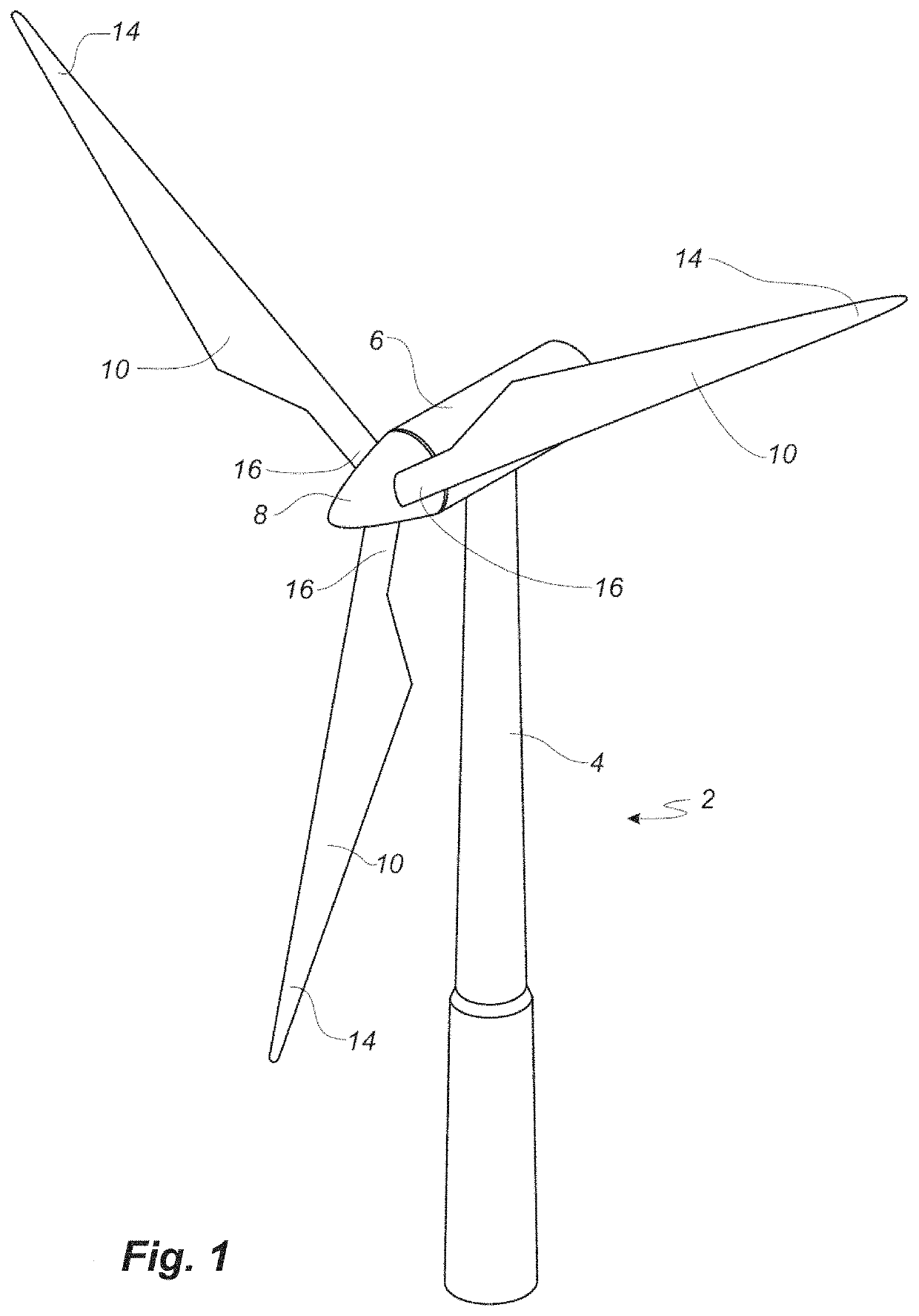
[0046]FIG. 1 shows a wind turbine,

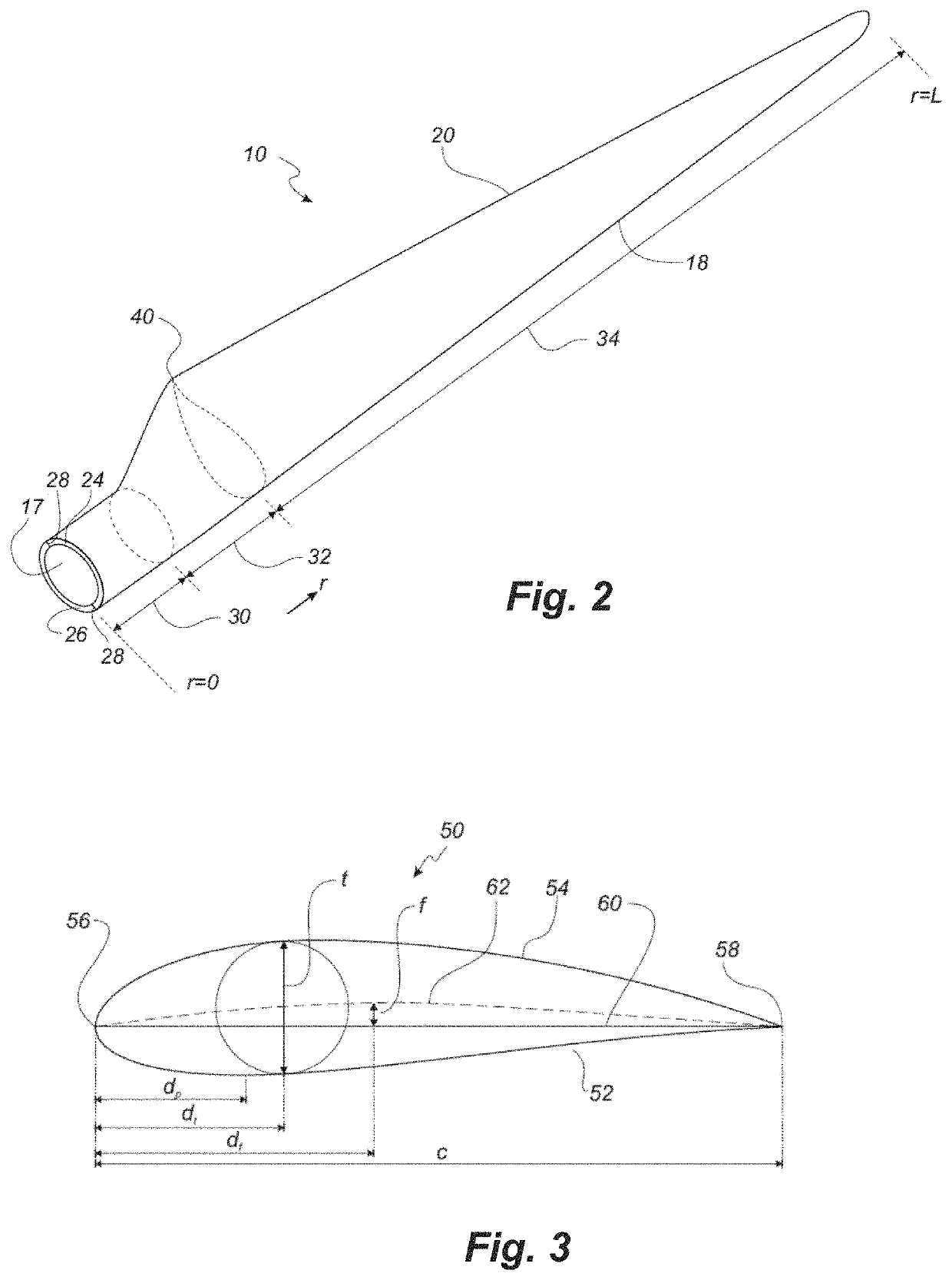
[0047]FIG. 2 shows a schematic view of a wind turbine blade,

[0048]FIG. 3 shows a schematic view of an airfoil profile through section I-I of FIG. 4,

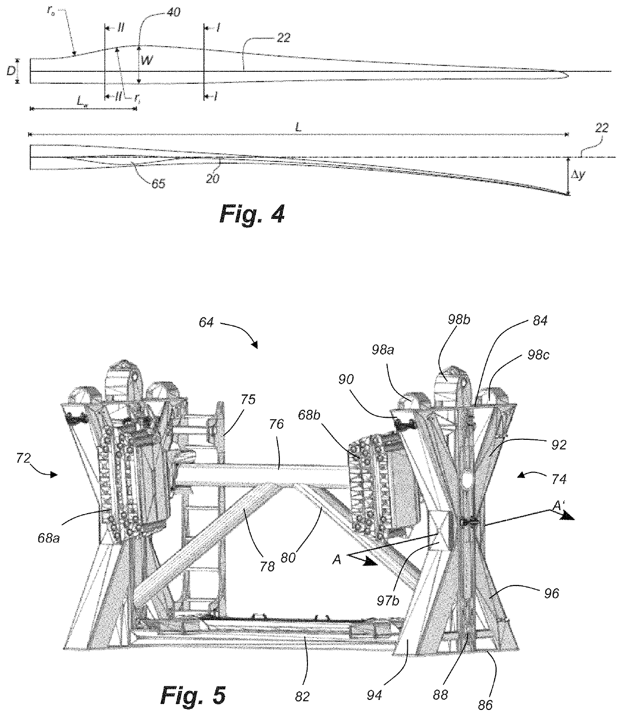
[0049]FIG. 4 shows a schematic view of the wind turbine blade, seen from above and from the side,

[0050]FIG. 5 shows a perspective view of a root frame assembly according to the present invention,

[0051]FIG. 6 shows another perspective view of a root frame assembly according to the present invention,

[0052]FIG. 7 is a sectional view along the line A-A′ in FIG. 5,

[0053]FIG. 8 is a top view of a bottom member of a root frame assembly according to the present invention,

[0054]FIG. 9 is a sectional view along the line B-B′ in FIG. 6,

[0055]FIG. 10 is a perspective view of a root end receptacle according to the present invention, and

[0056]FIG. 11 is a perspective view of another type of root end receptacle...


PUM


Abstract

The present invention relates to a transportation and storage system for a wind turbine blade (10), the system comprising a root frame assembly and a tip frame assembly. The frame assemblies comprise lateral frame parts (72, 74) each having a top member (84), a bottom member (86), a center beam (88), a first and a second upper inclined beam (90, 92) and a first and a second lower inclined beam (94, 96). The present invention also relates to the use of the system for transporting and / or storing one or more wind turbine blades.

Description

[0001]This is a National Phase Application filed under 35 U.S.C. 371 as a national stage of PCT / EP2017 / 071953, filed Sep. 1, 2017, an application claiming the benefit of European Application No. 16186986.2, filed Sep. 2, 2016, the content of each of which is hereby incorporated by reference in its entirety.FIELD OF THE INVENTION[0002]The present invention relates to a transportation and storage system for a wind turbine blade. In another aspect, the present invention relates to the use of the system for transporting and / or storing one or more wind turbine blades.BACKGROUND OF THE INVENTION[0003]Wind power is becoming increasingly popular due to its clean and environmentally friendly production of energy. The rotor blades of modern wind turbines capture kinetic wind energy by using sophisticated blade design created to maximize efficiency. Turbine blades may today exceed 80 metres in length and 4 metres in width. The blades are typically made from a fibre-reinforced polymer material ...

Claims


Application Information

Patent Timeline
Patent Type & Authority Patents(United States)
IPC IPC(8): F03D13/40F03D13/00
CPCF03D13/40F03D13/00F05B2240/221Y02E10/72F05B2260/02
Inventor BANGAR, RAHULVAN DER ZEE, JACOBUSOLESEN, NIKOLAJ
Owner LM WIND POWER US TECH APS
Learn More