
Method for predicting structure shape deformations

a technology of deformation and shape prediction, applied in the direction of structural/machine measurement, electrical/magnetic measurement arrangement, instruments, etc., can solve the problem that the strain sensor cannot only measure the strain of the surface and not the deformation shape, and achieve accurate shape prediction

Active Publication Date: 2020-08-04
NASA
View PDF2 Cites 1 Cited by
  • Summary
  • Abstract
  • Description
  • Claims
  • Application Information

AI Technical Summary

Benefits of technology

The present invention is about a way to measure the bending of flexible structures to track their shape in real-time. This allows for active control of the structure shape, and is done using new Curved Displacement Transfer Functions that can accurately predict the shape of the structure when it is bent to large degrees. The technical effect of this invention is that it provides a reliable and efficient means to control the shape of flexible structures in real-time.

Problems solved by technology

Strain sensors can only measure surface strains and not the deformed shape.

Method used


Image

  • Method for predicting structure shape deformations
  • Method for predicting structure shape deformations
  • Method for predicting structure shape deformations

Examples


Embodiment Construction

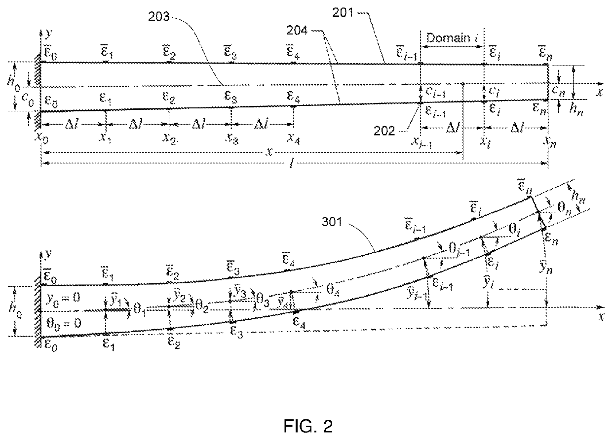
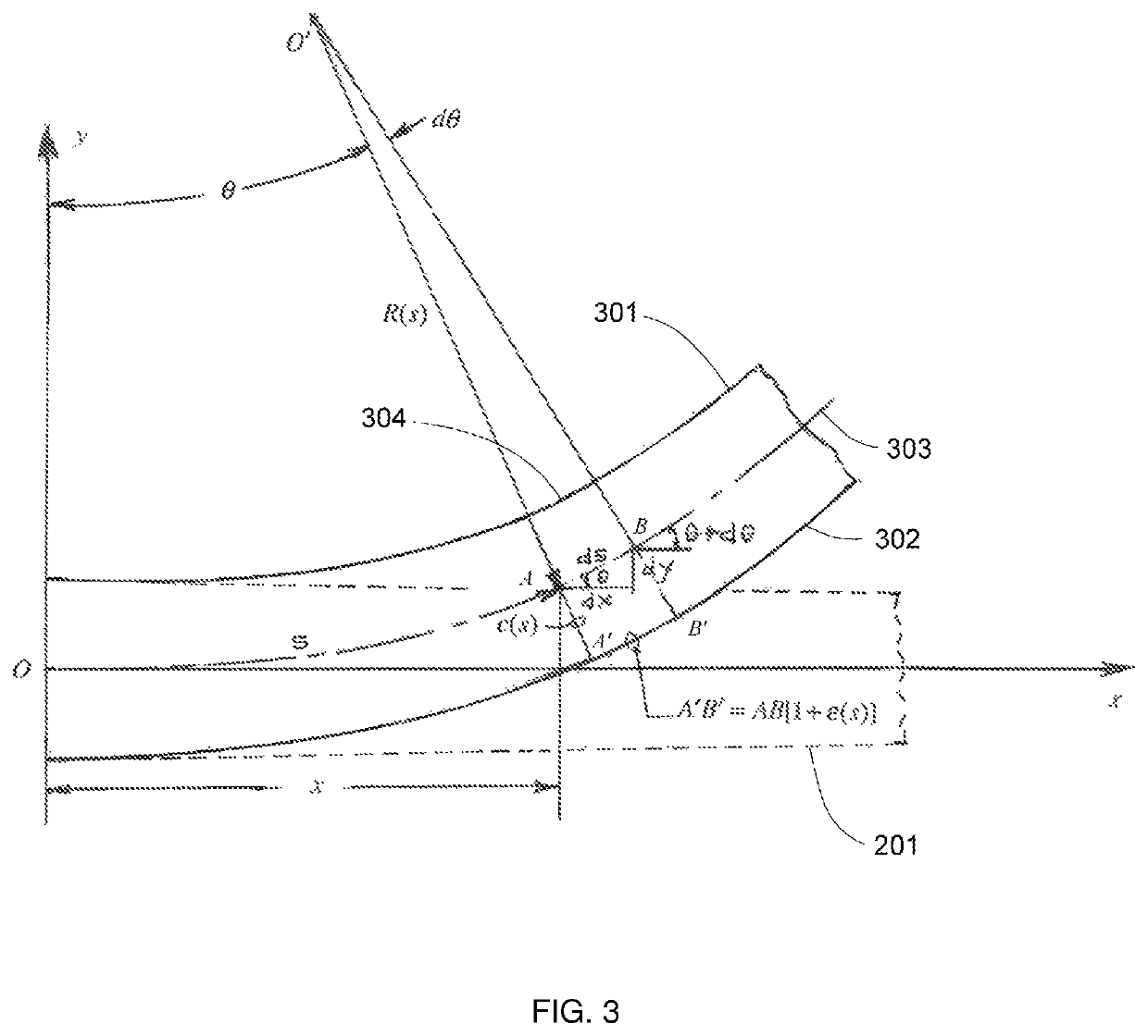
[0015]The invention, as embodied herein, comprises a method of obtaining curved displacement of a flexible structure by using strain measurements taken along the structure. For the present invention, the term displacement is defined as deformation of a structure out of the plane of the structure as applied to the structure's neutral axis 203. The term neutral axis is defined as the axis obtained by determining the axis or center point at each cross section of the structure.

[0016]To formulate the displacement theory, strain-sensing stations (strain measurement points) 202 are to be discretely distributed along a strain-sensing line on the surface of the structure (e.g., aircraft wing) as shown in FIG. 2. The depth-wise cross section of the structure along the strain-sensing line is called an imaginary “embedded beam”201 (not to be confused with the classical isolated Euler-Bernoulli beam). Each embedded beam 201 was then discretized into multiple domains (strain-sensing station separ...


PUM


Abstract

The invention is a method for obtaining the curved displacement of a flexible structure by using strain measurements obtained by strain sensors. By obtaining the displacement of structures in this manner, one may accurately construct the deformed shape of the structure under large geometric nonlinear deformations and display said deformed shape in real-time, enabling active control of the structure shape if desired.

Description

CROSS-REFERENCE TO RELATED APPLICATIONS[0001]The present application claims the benefit of provisional patent application Ser. No. 62 / 407,343, filed Oct. 12, 2016 by the present inventor(s), which is incorporated by reference in its entirety. U.S. Pat. No. 7,520,176, issued Apr. 21, 2009 by the present inventor(s), is hereby incorporated by reference.STATEMENT OF GOVERNMENT INTEREST[0002]The invention described herein may be manufactured and used by or for the Government of the United States of America for governmental purposes without payment of any royalties thereon or therefor.FIELD OF THE INVENTION[0003]The present invention relates to deformable structures, and more specifically to predicting shape deformations of deformable structures.BACKGROUND OF THE INVENTION[0004]The Helios prototype (wing span 247 ft.) broke-up in mid-air at an altitude of 2,800 feet under very large wing dihedral deformation (wing tip deflection reaching 40 ft.). Flexible structures, such as the wings on...

Claims


Application Information

Patent Timeline
Patent Type & Authority Patents(United States)
IPC IPC(8): G01M5/00G01B7/16
CPCG01M5/0041G01B7/16G01M5/0016G01B21/32
Inventor KO, WILLIAM LFLEISCHER, VAN TLUNG, SHUN-FAT
Owner NASA
Learn More