
Flexible torsion shaft and an arrangement using it and a cleaning device for air-conditioning ducts

a technology of flexible torsion shaft and cleaning device, which is applied in the direction of shaft for rotary movement, cleaning of hollow articles, brushes, etc., can solve the problems of steel cable weight as much as several tens of kilograms, and achieve the effect of reducing friction and stiffness and tensile strength

Active Publication Date: 2020-08-11
BIERKUHL OY
View PDF17 Cites 0 Cited by
  • Summary
  • Abstract
  • Description
  • Claims
  • Application Information

AI Technical Summary

Benefits of technology

The solution provides a torsion shaft with high torsional strength and flexibility, significantly reducing weight and improving user-friendliness, enabling efficient and lightweight air-conditioning duct cleaning.

Problems solved by technology

A second drawback with this known solution is that the steel cable is heavy, with the reel weighing as much as several tens of kilograms.

Method used


Image

  • Flexible torsion shaft and an arrangement using it and a cleaning device for air-conditioning ducts
  • Flexible torsion shaft and an arrangement using it and a cleaning device for air-conditioning ducts
  • Flexible torsion shaft and an arrangement using it and a cleaning device for air-conditioning ducts

Examples


Embodiment Construction

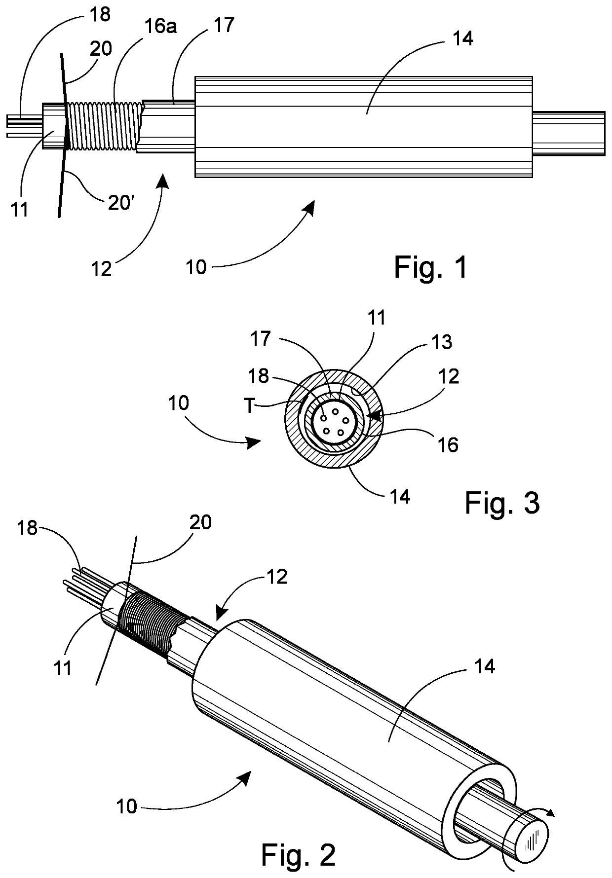
[0024]The components of the flexible shaft arrangement 10 are a casing tube 14 and the torsion shaft 12 itself. The length of the shaft arrangement can be 1-40 m and the diameter of the torsion shaft 12, 4-20 mm.

[0025]The casing tube 14 is typically of polyamide and is intended to protect structures by keeping the rotating torsion shaft 12 away from, e.g. the duct structures. Polyamide has a low coefficient of friction with most of the polymers binding the reinforcing fibers, such as epoxy or polyurethane. A particularly advantageous totality is achieved if the flexible shaft is coated with polytetrafluorethylene, i.e. PTFE (Teflon®). Alternatively, the inner surface 13 of the protective tube is covered with a layer T of PTFE (FIG. 3).

[0026]The body of the torsion shaft 12 of FIG. 1 is of epoxy and filament wires 20, 20′, generally of glass fiber, are wound on top of it in two directions. In this case, the core is a bunch of fibers 18 and a polyethylene membrane 11 is on top of it. ...


PUM

PropertyMeasurementUnit
elongationaaaaaaaaaa
diameteraaaaaaaaaa
winding angleaaaaaaaaaa

Abstract

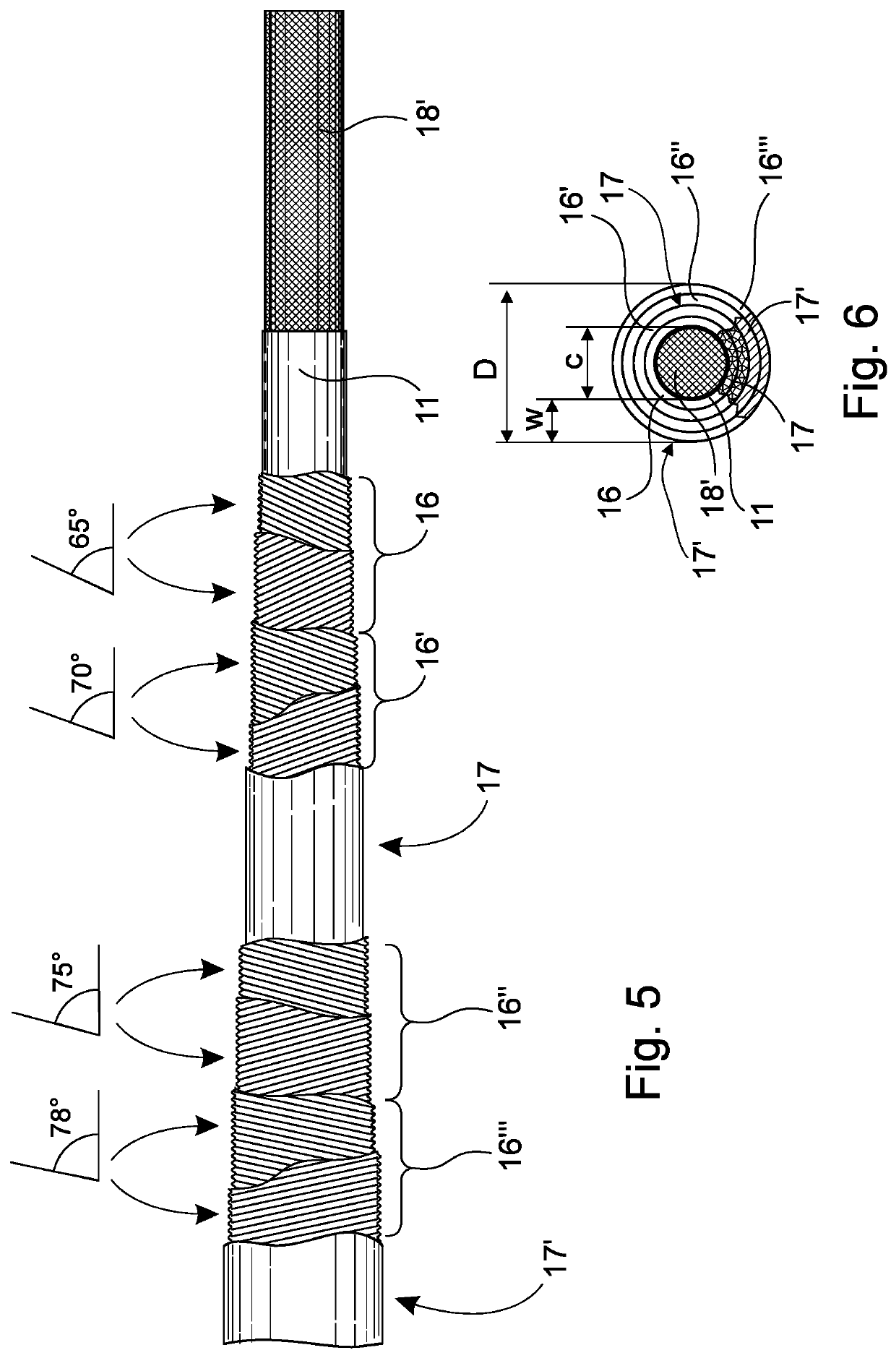
A flexible composite torsion shaft for attachment to a drive shaft includes an elongated core element having a circular cross section. A reinforcement comprising at least one polymer layer and multiple layers of reinforcing-fiber wound around the core element inside the at least one polymer layer. Each reinforcing-fiber layer is wound around the core element at a winding angle in a range of 40° to the hoop winding angle, depending on a width of a reinforcing-fiber being wound, relative to a longitudinal direction of the core element. At least one reinforcing-fiber-layer is wound at an opposite angle from another reinforcing-fiber layer inside the at least one polymer layer. The winding angle increases as an average layer diameter of reinforcing-fiber insider the at least one polymer layer increases.

Description

CROSS-REFERENCE TO RELATED APPLICATIONS[0001]This application is a continuation-in-part of International Patent Application No. PCT / FI2016 / 050146, filed Mar. 10, 2016, designating the United States, and claiming benefit of Finland Patent Application No. 20155157, filed Mar. 10, 2015, and Finland Patent Application No. 20165025, filed Jan. 15, 2016, the disclosures of which are incorporated herein by reference in their entirety.FIELD OF THE INVENTION[0002]The present invention relates to a flexible torsion shaft for attachment to a drive shaft, as well as an arrangement using a casing tube. A cleaning device for air-conditioning ducts is one particular application.BACKGROUND OF THE INVENTION[0003]The flexible shaft according to the invention is suitable for transmitting a torsion force in many applications, particularly when used inside a casing tube. In particular, this case, discloses an air-conditioning cleaning device, which is known from, among others, Finnish patents 94221 and ...

Claims


Application Information

Patent Timeline
Patent Type & Authority Patents(United States)
IPC IPC(8): A46B13/02F16C1/02A46B5/00B08B9/045B08B1/04
CPCB08B1/04A46B5/0037B08B9/045F16C1/02A46B13/02A46B2200/3013B08B1/34B08B1/32
Inventor HILTUNEN, PENTTI
Owner BIERKUHL OY
Learn More