Apparatus for connecting oxygen delivery control instrument to patient delivery device

Active Publication Date: 2020-08-11
DYNASTHETICS
View PDF10 Cites 7 Cited by
  • Summary
  • Abstract
  • Description
  • Claims
  • Application Information

AI Technical Summary

Benefits of technology

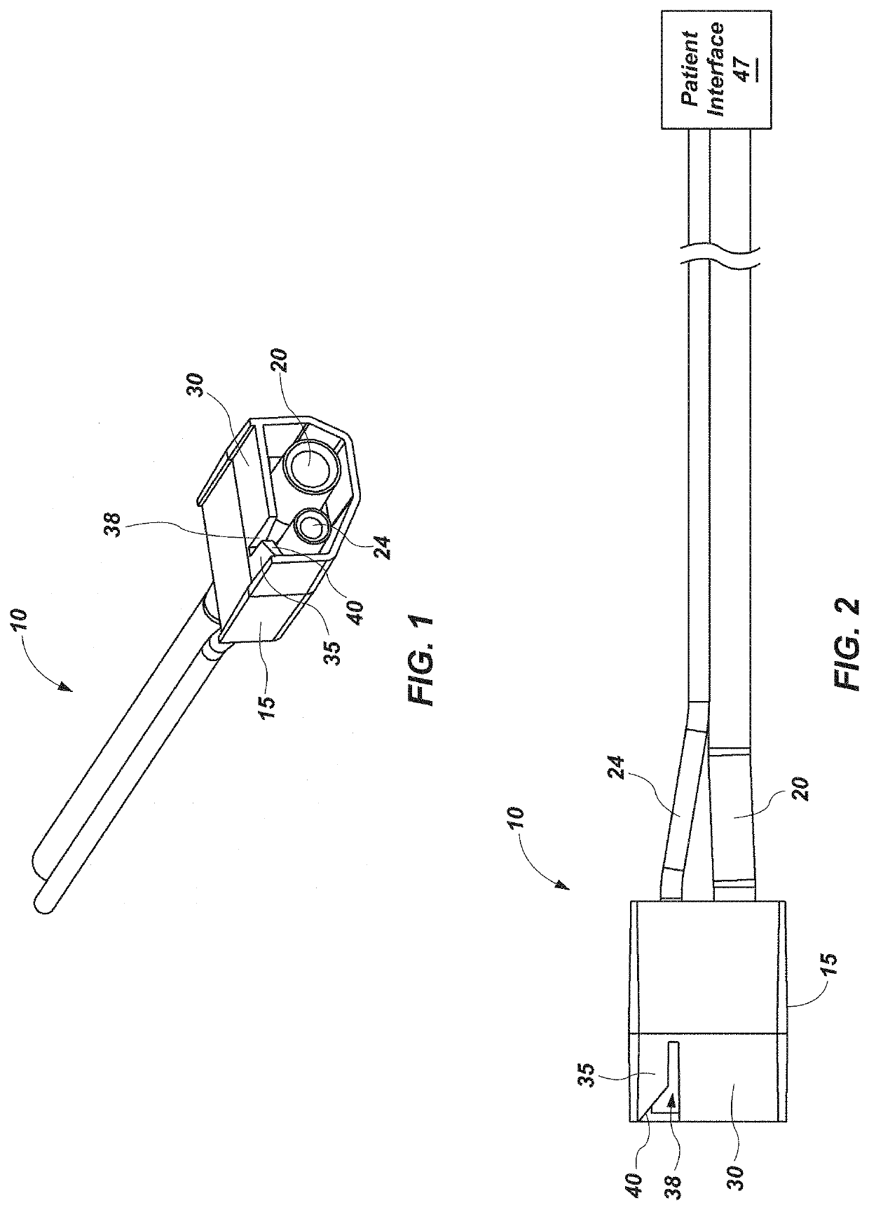
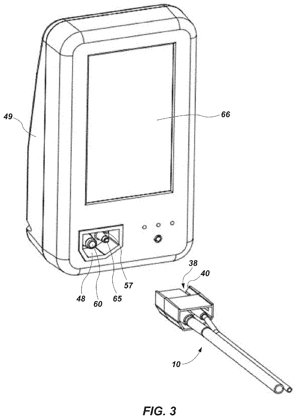
[0011]According to another aspect, a connector is described herein, the connector including: a housing, the housing having a top surface extending from a first side to a second side, the top surface comprising a patient interface encoding portion and a depth measurement insertion portion, and wherein an open slot in the top surface of the housing separates the patient interface encoding portion and the depth measurement insertion portion; wherein the patient interface encoding portion of the housing comprises means to enable identification of information relating to the patient interface; wherein the depth measurement insertion portion of the housing comprises means to enable measurement of a depth of the housing within the oxygen delivery control device; and wherein the housing encloses a first lumen and a second lumen, the first lumen for conveying pressurized oxygen and the second lumen for measuring of intra-nasal pressure at the patient interface, the second lumen having a smaller diameter than the first lumen.
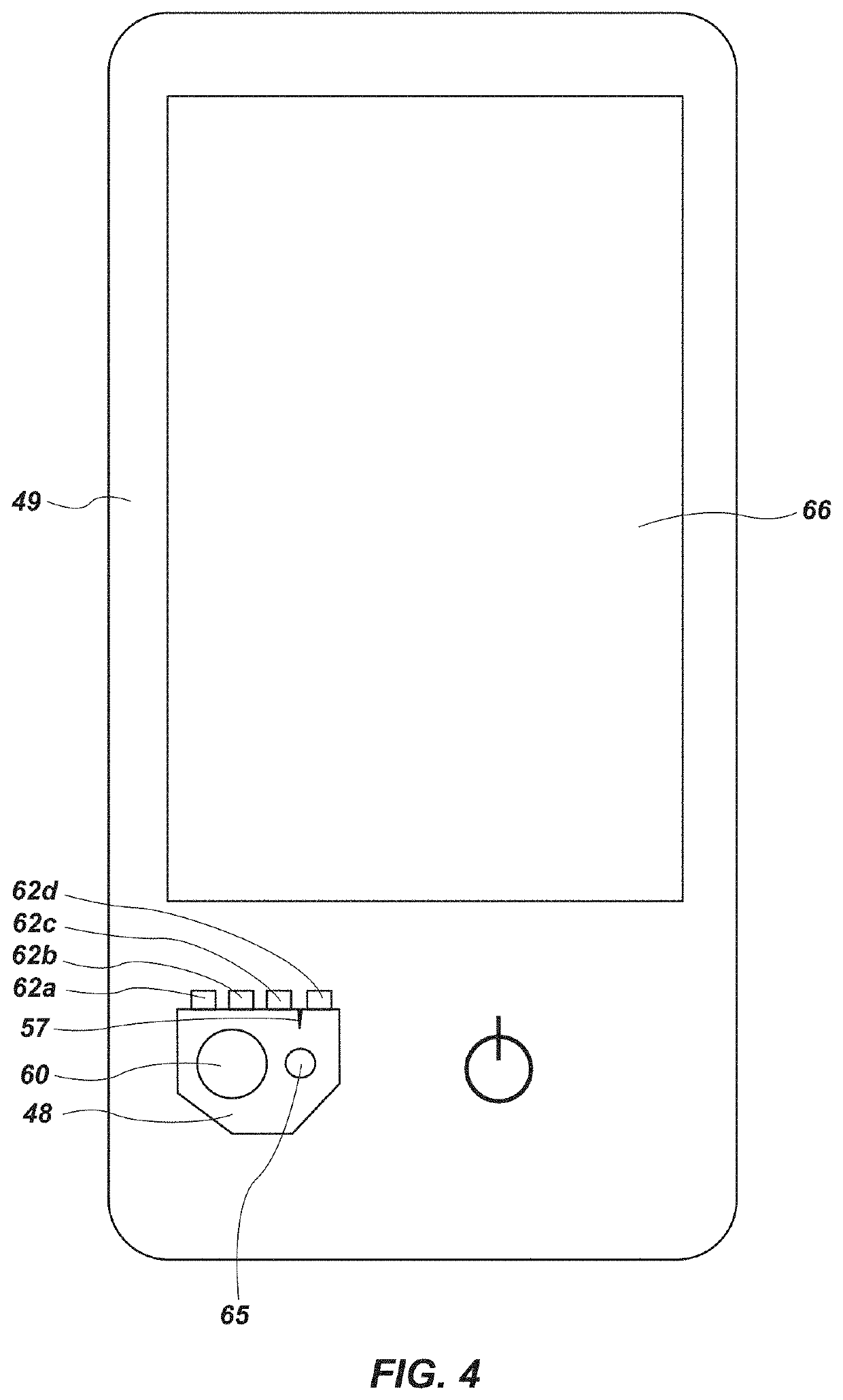
[0012]In some configurations, the open slot may be positioned closer to the second side of the housing. In some configurations, the means to enable identification of information relating to the patient interface comprises means for optical detection, for example, at least two reflective pads, the at least two reflective pads configured to reflect infrared light at one of high reflectivity, low reflectivity, and intermediate reflectivity.
[0013]According to another aspect, the means to enable detection of a depth of the housing within the oxygen delivery control device comprises at least one of: a triangle printed on the depth insertion portion, a gradient printed on the depth insertion portion, an angled cut-away formed in the depth insertion portion, and a reflective pad placed on the depth insertion portion. The means to enable detection of a depth of the housing within the oxygen delivery control device, in some configurations, comprises a continuously variable reflective pad. In some configurations, a third lumen may be provided to enable end-tidal CO2 measurement, the third lumen having a diameter smaller than the diameter of the first lumen.
[0014]According to yet another aspect, a system for delivering oxygen to a patient may include: a patient interface; an oxygen delivery control device comprising a receptacle with an optical isolation wall formed therein; and a connector for connection the patient interface to the oxygen delivery control device, the connector comprising: a first lumen for conveying pressurized o

Problems solved by technology

Many respiratory systems are characterized by complexity and diversity of possible applications.
Different interfaces usually have to be connected using means of connection, and in some cases this can give rise to an increased risk of error and po

Method used


Image

  • Apparatus for connecting oxygen delivery control instrument to patient delivery device
  • Apparatus for connecting oxygen delivery control instrument to patient delivery device
  • Apparatus for connecting oxygen delivery control instrument to patient delivery device

Examples


Embodiment Construction

[0036]The following provides a detailed description of particular embodiments of the present invention. Reference will now be made to the drawings in which the various elements of the illustrated configurations will be given numerical designations and in which the invention will be discussed so as to enable one skilled in the art to make and use the invention. It is to be understood that the following description is only exemplary of the principles of the present invention, and should not be viewed as narrowing the scope of the claims which follow, which claims define the full scope of the invention.

[0037]It will be appreciated that various aspects discussed in one drawing may be present and / or used in conjunction with the embodiment shown in another drawing, and each element shown in multiple drawings may be discussed only once. For example, in some cases, detailed description of well-known items or repeated description of substantially the same configurations may be omitted. This ...


PUM


Abstract

A connector for connecting an oxygen delivery device to a patient interface. The connector includes a housing with a first lumen for delivering oxygen and a second lumen to allow pressure to be measured. A third optional lumen may allow for gas sampling. The housing surrounding the first and second lumen has a portion that includes encoding for determining the type of patient interface being used, as well as a depth indicator sensor.

Description

TECHNICAL FIELD[0001]The present disclosure relates generally to a system and method to deliver oxygen to a patient from an oxygen delivery device to a patient interface. More specifically, the present disclosure relates to a method and apparatus for connecting a patient interface and an oxygen delivery device.BACKGROUND[0002]Oxygen is often supplied to patients during medical procedures. Known methods for regulating oxygen supply may provide increased benefits for patient safety. Such systems are disclosed, for example, in U.S. Pat. Nos. 10,159,815 and 10,143,820, which are incorporated herein in their entireties. Many respiratory systems are characterized by complexity and diversity of possible applications. Often, a plurality of components must be connected before a respiratory system is used.[0003]Different interfaces usually have to be connected using means of connection, and in some cases this can give rise to an increased risk of error and possibly cause a dangerous situation...

Claims


Application Information

Patent Timeline
IPC IPC(8): A61M16/08A61M16/00
CPCA61M16/085A61M16/022A61M16/0858A61M16/0875A61M2016/003A61M2205/3306A61M2205/14A61M2202/0208A61M11/00A61M16/0051A61M16/0816A61M2016/0027A61M2205/18A61M2205/3313A61M2205/50A61M2205/6018A61M2205/6036A61M2205/6045A61M2205/6063A61M2230/432A61M2240/00A61M16/0672A61M16/024A61M2202/0007
Inventor ORR, JOSEPHBURK, KYLE M.YOUNGBERG, ERICSAKATA, DEREK
Owner DYNASTHETICS
Why Eureka
Try Eureka