Unlock instant, AI-driven research and patent intelligence for your innovation.

Manipulation device

a technology of manipulator and magnetic field, which is applied in the direction of mechanical control device, shock absorber, instruments, etc., can solve the problems of large magnetic field, poor manipulation feeling, and given to the manipulator, and achieves superior manipulation feeling and low hardness.

Active Publication Date: 2020-08-11
ALPS ALPINE CO LTD
View PDF13 Cites 1 Cited by
  • Summary
  • Abstract
  • Description
  • Claims
  • Application Information

AI Technical Summary

Benefits of technology

The device achieves superior manipulation feeling with reduced noise and enables downsizing by effectively applying rotational loads through magnetic viscous fluid alignment, enhancing user interaction without motor power consumption.

Problems solved by technology

Therefore, there has been the problem that annoyance or the like is given to the manipulator and manipulation feeling is worsened.
However, to change the viscosity of the magnetic viscous fluid filled in the widened gap, a large magnetic field is needed.
Therefore, the coil that generates that magnetic field and the yoke that induces the magnetic field must be enlarged, so there has been another problem that belies the purpose of achieving downsizing.

Method used


Image

  • Manipulation device
  • Manipulation device
  • Manipulation device

Examples


first embodiment

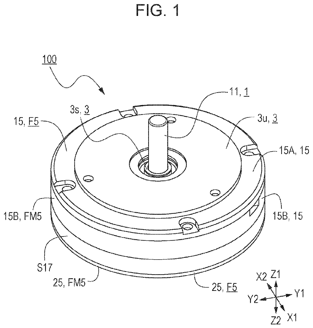
[0044]FIG. 1 is a top perspective view of a manipulation device 100 according to a first embodiment of the present invention. FIG. 2 is an exploded perspective view of the manipulation device 100. FIG. 3A is a top view when viewed from the Z1 side indicated in FIG. 1, and FIG. 3B is a front view when viewed from the Y2 side indicated in FIG. 1. FIG. 4 is a cross-sectional view taken along line IV-IV indicated in FIG. 3A.

[0045]The manipulation device 100 in the first embodiment of the present invention has an appearance as illustrated in FIGS. 1 and 3. As illustrated in FIG. 2, the manipulation device 100 is mainly structured by having a manipulation member 1 with a manipulation body 11 that operates in a manipulation direction due to a manipulation by the manipulator, a support body 3 that freely supports the operation of the manipulation body 11, a movable load imparting mechanism F5 that imparts a load to the manipulation body 11, and a first buffering layer K16 and a second buffe...


PUM


Abstract

A manipulation device has a manipulation body operated by the manipulator in a manipulation direction, a support body freely supporting the operation of the manipulation body, and a movable load imparting mechanism imparting a load to the manipulation body. The movable load imparting mechanism has a movable member engaged with the movable axis of the manipulation body, a magnetism generating mechanism having a coil that generates a magnetic field and a first yoke provided so as to enclose the coil, and a magnetic viscous fluid, its viscosity changing according to the strength of a magnetic field. The magnetic viscous fluid is filled in a first gap between the first yoke and the movable member. In the gap, a first buffering layer not harder than the movable member is provided on at least one of the opposing plane of the first yoke and the opposing plane of the movable member.

Description

CLAIM OF PRIORITY[0001]This application is a Continuation of International Application No. PCT / JP2017 / 005256 filed on Feb. 14, 2017, which claims benefit of Japanese Patent Application No. 2016-036429 filed on Feb. 26, 2016. The entire contents of each application noted above are hereby incorporated by reference.BACKGROUND OF THE INVENTION[0002]1. Field of the Invention[0003]The present invention relates to a manipulation device that can give a manipulation feeling to a manipulator in response to a manipulation by the manipulator.[0004]2. Description of the Related Art[0005]Recently, various manipulation devices with a force feedback function are proposed. When the manipulator manipulates a manipulation member, these various manipulation devices impart an external force (sense of force) such as a resistance force or thrust that matches the amount of manipulation of the manipulation member and its manipulation direction so that a manipulation feeling can be made superior and a desire...

Claims


Application Information

Patent Timeline
Patent Type & Authority Patents(United States)
IPC IPC(8): F16F9/12G05G5/08F16F9/53G05G1/08G05G5/03
CPCG05G5/03F16F9/535F16F9/12G05G5/08F16F2224/045G05G1/08
Inventor TAKAHASHI, KAZUNARIGOTO, ATSUSHI
Owner ALPS ALPINE CO LTD