Method and system for determining optimized travel path for agricultural implement on land with obstacle

a technology of agricultural implements and travel paths, applied in forecasting, data processing applications, instruments, etc., can solve problems such as inefficiency and potential waste of time and energy resources, negative impact on production activities, and difficulty in determining travel paths, so as to reduce inefficiencies

Active Publication Date: 2020-08-11
VERGE TECH INC
View PDF5 Cites 25 Cited by
  • Summary
  • Abstract
  • Description
  • Claims
  • Application Information

AI Technical Summary

Benefits of technology

[0007]The present invention is accordingly primarily directed to a method for optimizing the travel path of an agricultural implement, such that a producer can attempt to reduce the inefficiencies arising from an in-field obstacle or obstruction, although other means of optimizing the workflow are disclosed herein.
[0037]The present invention is directed to selecting one of a plurality of possible travel paths, each of which provides a path to cover the same field, based on a comparison using set predetermined criteria or parameters. The selected or “optimized” travel path, however, could be determined based on various parameters. As one example, comparing possible travel paths to determine which would have the shorter distance is one non-exhaustive way to establish an optimized travel path, where distance is determined to represent fuel consumption and / or exhaust emissions and thus an optimized travel path would be one having reduced fuel consumption and / or exhaust emissions. However, other parameters or criteria could be employed when comparing the possible travel paths. For example, time may be the target criteria, and specifically reducing the time spent on the path—even where the quickest route may actually embody a slightly longer path than an alternative path. Operational costs or raw material costs provide yet another example, where shortest distance may not equate to reduced costs. Optimization could be directed to reducing soil erosion, compaction or top soil pulverization (looking, for example, to land use, slope position, and soil organic and inorganic variables), or reducing negative water quality impact (such as by adding buffer zones—slopes, soils, etc.—to define “buffer obstacles”).
[0039]In addition to optimized travel across an entire field, embodiments of the present invention may be used to optimized overlap of adjacent rows, which can be useful in reducing input costs, for example seed, fertilizer and chemical additives. Further, embodiments according to the present invention could be used to assess the effects of field boundary increases and decreases, thus providing another means to provide an optimized travel path.
[0041]Optimization of work flow in agricultural production may thus include reducing distance travelled. The reduction in distance travelled through planning and computer simulation can reduce the time required for the selected field activity. Additional effects of such optimization may include improved workflow for multiple implements / units used in an agricultural field while reducing total distance travelled and time required. While the distance travelled may be optimized through computer simulation and field planning prior to entry, time may also be reduced when multiple pieces of equipment are utilizing the reduced distance and operation is coordinated.
[0043]Agricultural production and equipment support require planning and analysis of crop input load and unload travel patterns and locations. Although the primary agricultural equipment is provided with an optimized field plan in some exemplary embodiments of the present invention, the support equipment suppling seed, fertilizer, pesticides and / or removing the agricultural product may also benefit from field management, planning and optimization to reduce distance travelled and time expended. Positioning and determination of load and unload areas for support equipment for inputs and harvest removal should also be optimized where appropriate, including field entry and exit optimization (optimized path calculating possible entry and exit points start to finish per field) and field to field optimization (optimized path calculating possible field to field entry and exit points).
[0045]In addition, travel plan optimization according to embodiments of the present invention may also reduce personal stresses arising from field and farm management, which optimization may then be seen as enhancing productivity and safety.

Problems solved by technology

However, it is well known in the art of production from agricultural land that physical obstacles and obstructions are common and that the presence of such can negatively impact production activities.
For example, natural obstacles such as water bodies can block a farmer's ability to move the selected implement in straight, uninterrupted rows, instead forcing the farmer to redirect the implement around the obstacle and thereby introduce inefficiencies and potential waste of time and energy resources, such as due to going over the same patch of land two or more times as you work around the obstacle from different angles.
It can be challenging to determine a travel path for the selected implement that covers the land as efficiently as possible so as to reduce resource waste.
In addition, man-made obstacles are increasingly making an impact on agricultural production.
As is the case with natural obstacles, redundant implement travel can result from the irregular remaining land that must be acted upon, with the resultant resource waste.
While producers may attempt, with varying degrees of success, to determine an optimized way to farm the remaining land in the now-disturbed field, it is a challenging task that commonly results in a less-than-optimal approach.
The results are often unsatisfactory, and efforts to compensate farmers for lost production are hampered by uncertainty around the quantum of loss.

Method used


Image

  • Method and system for determining optimized travel path for agricultural implement on land with obstacle
  • Method and system for determining optimized travel path for agricultural implement on land with obstacle
  • Method and system for determining optimized travel path for agricultural implement on land with obstacle

Examples


Embodiment Construction

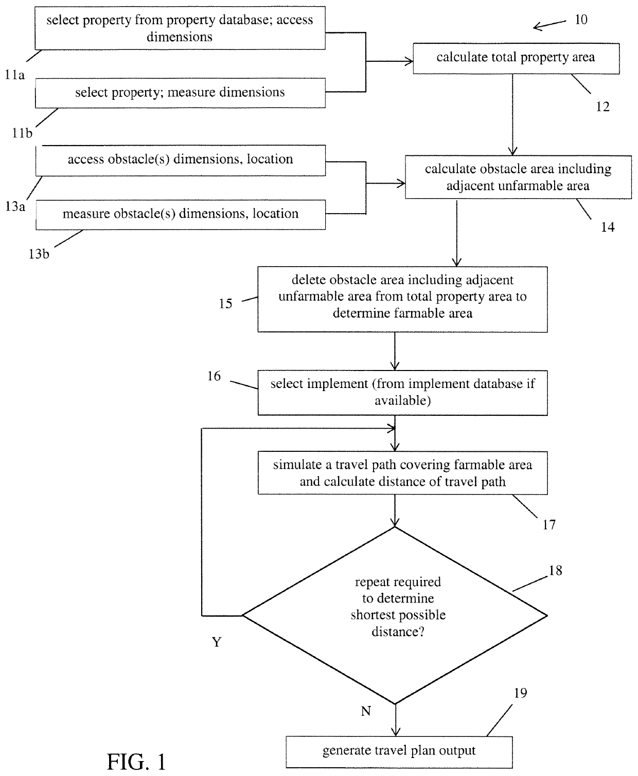
[0057]The present invention is directed to methods for identifying and addressing the impact on agricultural production of a physical obstacle—natural or man-made—that is located in a field. Reference is made to pre-disturbance and post-disturbance land areas, which respectively represent the farmable land before and after introduction of the obstacle. In the case of a man-made obstacle, the method may address a situation where the obstacle is already in place, or it may address a situation where the obstacle has yet to be positioned in the field. As stated above, a travel path may be selected as “optimized” based on various criteria and parameters, depending on what the operator has determined is the factor to be determinative in selecting between possible paths. One common feature of the exemplary methods described below is the determination of a post-disturbance farmable area, and how one can optimize production by analysis of that farmable area and determination of an implement ...


PUM


Abstract

Methods for identifying and addressing inefficiencies in agricultural production activities caused by physical obstacles in the target field. A method and system is disclosed for determining an optimized travel path for an agricultural implement, specifically in the presence of an obstacle or obstruction such as an access road, oil well or public utility infrastructure. The method may further comprise means for determining the impact of such obstacle or obstruction on production from the agricultural land, as well as means for determining an optimized implement type and configuration. One or more travel path plans may be generated for selection of one by an agricultural producer. The method may also comprise means for determining an optimized location or position within a plot of land for an obstacle or obstruction that has not yet been constructed, as a way to reduce or alleviate the negative impact of such obstacle or obstruction on production from the plot of land.

Description

FIELD OF THE INVENTION[0001]The present invention relates to methods of agricultural production, and specifically to methods for enhancing production through determination of optimized work plans.BACKGROUND OF THE INVENTION[0002]Agricultural activity such as seeding or harvesting is commonly undertaken using selected implements and driving or pulling such implements across the land in a sequence of generally parallel rows, with only modest overlap dictated primarily by the implement itself. It is obvious that the most optimized and beneficial situation is one in which the land can be farmed in a series of straight, uninterrupted rows, back and forth from one end of the field to the other as one works across the field. No wasted implement movement is necessary, and no energy or time is therefore wasted.[0003]However, it is well known in the art of production from agricultural land that physical obstacles and obstructions are common and that the presence of such can negatively impact ...

Claims


Application Information

Patent Timeline
Patent Type & Authority Patents(United States)
IPC IPC(8): G06Q10/04G06Q50/02
CPCG06Q10/047G06Q50/02
Inventor STORY, LANE
Owner VERGE TECH INC
Why Eureka
Try Eureka