Breast pump and cap for same

a technology of a breast pump and a cap, which is applied in the direction of suction pumps, intravenous devices, suction devices, etc., can solve the problems of not being able to easily seal between two soft parts, and achieve the effect of moving and deformation better and facilitating the creation of suction curves

Active Publication Date: 2020-08-18
MEDELA HLDG AG
View PDF10 Cites 3 Cited by
  • Summary
  • Abstract
  • Description
  • Claims
  • Application Information

AI Technical Summary

Benefits of technology

[0009]The breast pump is thus assembled in a functioning manner by simply resting and snapping into place the rigid cap on the flexible pump diaphragm. The cap can thus be fitted just as easily or even more easily than the caps with protective diaphragm used until now with the Symphony pump. No additional fastening means are needed in order to connect the cap with the housing. Especially, the cap does not have to be fixed to the housing of the pump with fixing means such as screws or retaining hooks. The cap is only connected with the pump diaphragm.
[0012]A stop is preferably provided, up to which the cap can be put over the pump diaphragm. This makes it easier for the mother to identify whether the cap is fitted correctly and completely.
[0016]This cap can thus be fitted in a sealing and functional manner also to the pump diaphragm of the known Symphony pump without having to use an additional protective diaphragm.
[0022]The dome-like main body preferably transitions into an edge region that is chamfered in a manner widening outwardly and which transitions into a cylindrical edge region, the cylindrical edge region ending in the outermost edge. The circumferential bearing region is preferably formed in the region of transition from the main body into the chamfered edge region. This design also enables an optimal use with a pump diaphragm itself having a cylindrical collar or surface, as is the case for example with the pump diaphragm of the Symphony pump.
[0024]The at least one form-fit element is preferably designed as a snap-fit element. The at least one form-fit element is preferably an inwardly directed bead. The at least one form-fit element is preferably formed in a manner running around the inner side of the cap. A number of form-fit elements are preferably provided and are separated from one another by interruptions. Three form-fit elements and three interruptions are preferably provided. The three form-fit elements are preferably identical. This segment-like form fit can allow air to escape to a small extent from the chamber in the event of increased overpressure.
[0029]This type of venting is advantageous since the valve does not have to be arranged in the pump diaphragm. The pump diaphragm can thus move and deform better. The suction curves can be created more easily and in an optimized manner.

Problems solved by technology

Seals between two soft parts, however, are not so simple, and therefore the production of the cap, the protective diaphragm and the pump diaphragm is subject to strict specifications and requires sound knowledge accordingly.

Method used


Image

  • Breast pump and cap for same
  • Breast pump and cap for same
  • Breast pump and cap for same

Examples


Embodiment Construction

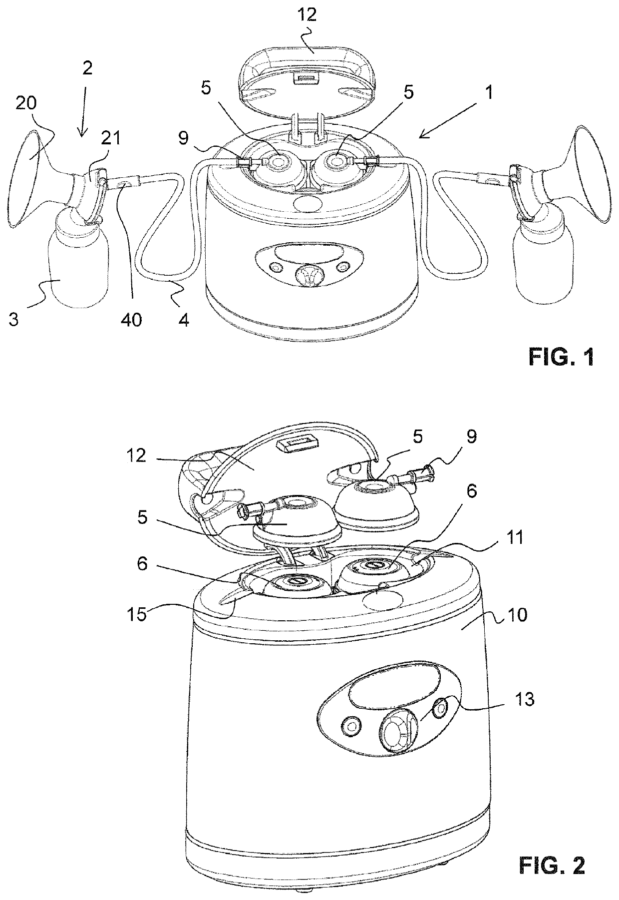
[0049]A breast pump unit having a breast pump 1 according to the invention is illustrated in FIG. 1. The breast pump 1 has a housing 10, which on the upper side thereof has an indentation 11. Two flexible pump diaphragms 6 are arranged in this indentation 11 and are connected via a driveshaft 14 to a pump mechanism driven by means of an electric motor.

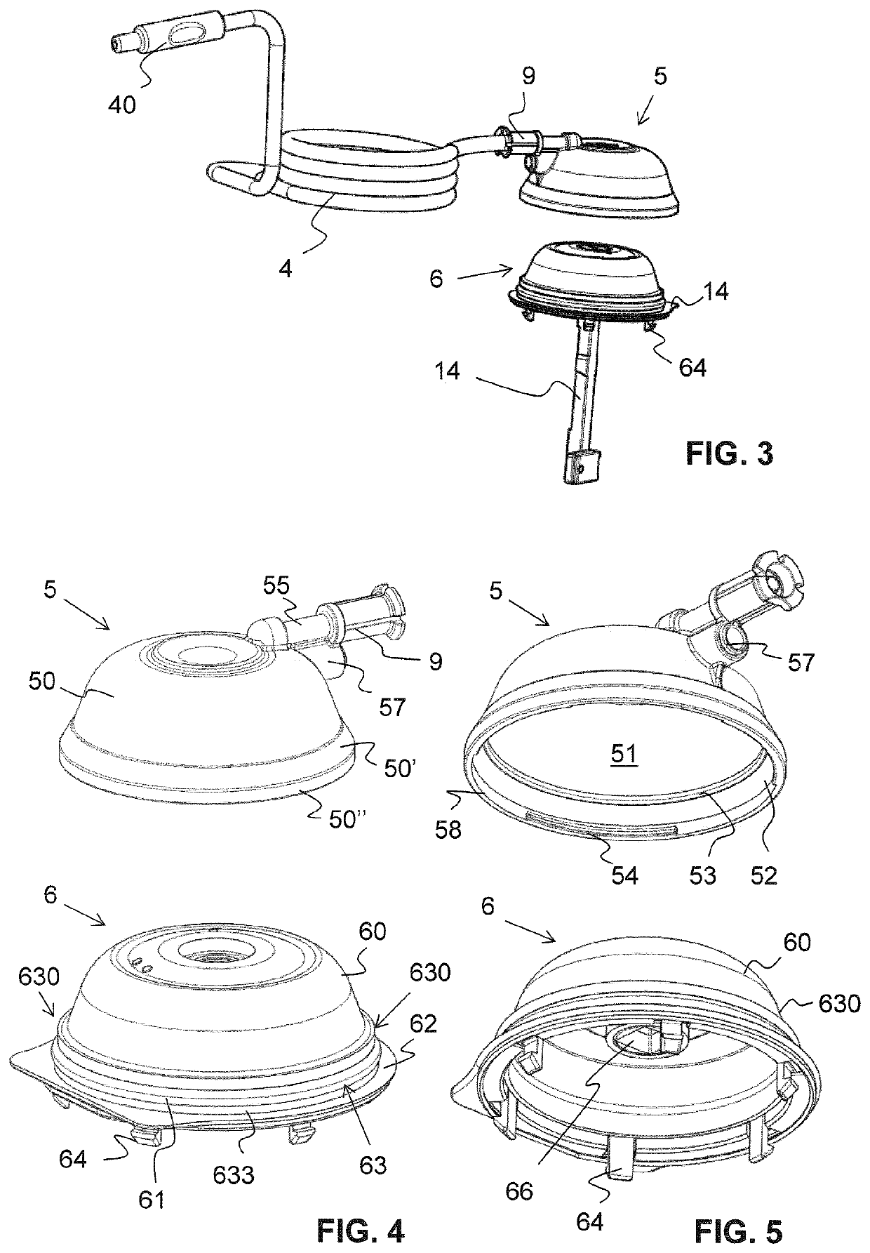
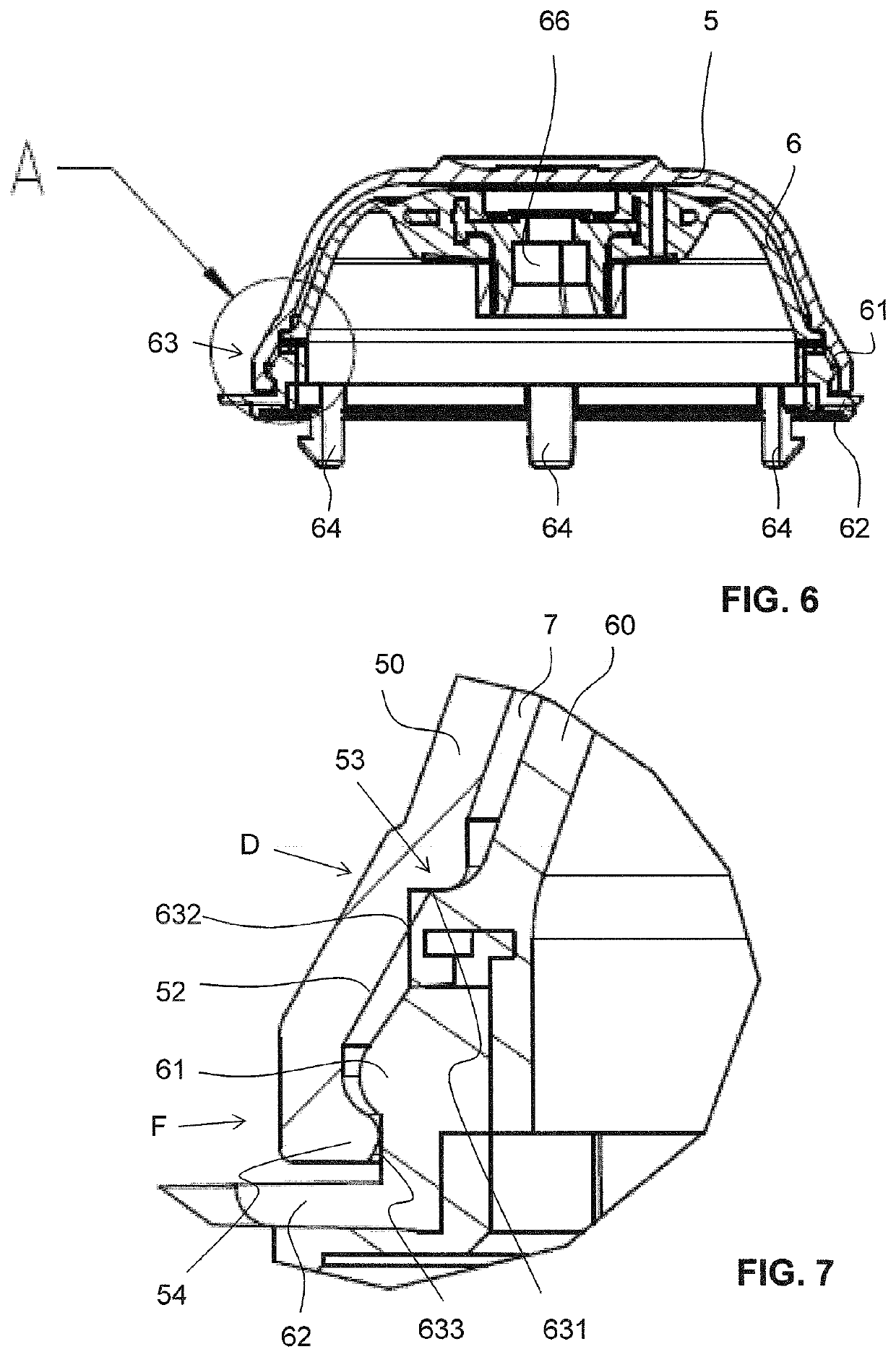
[0050]Each pump diaphragm 6 has a fixing plate 62 running around the periphery of said pump diaphragm and, on the underside thereof, latching hooks 64. The driveshaft 14 is likewise connected fixedly, but removably to the pump diaphragm 6, a corresponding fastening groove 66 being provided in the pump diaphragm for this purpose. The fastening groove 66 is preferably located in the upper middle region of the main body 60, such that the driveshaft 14 acts along the longitudinal centre axis of the pump diaphragm 6. By means of these connections, the pump diaphragm is held in a fixed manner in the housing 10 of the breast pump 1 and is usu...


PUM


Abstract

A breast pump for pumping human breast milk has a flexible pumping membrane and a stiff cap, which can be fitted onto said pumping membrane, this resulting in the formation of a pumping chamber for generating a negative pressure. The cap can be, or is, connected to a breast-shield unit via a suction line. The pumping membrane has an encircling collar with a step and a laterally projecting protrusion. The cap has, on its inner side, an encircling abutment region and also at least one form-fitting element, which is spaced apart from the encircling abutment region and establishes a form fit with the protrusion of the pumping membrane. The cap is positioned with a snap fit on the pumping membrane. In the abutment region (53), it establishes a joint frictional fit with a step of the pumping membrane and thus forms a seal. The snap-fit positioning of the cap on the pumping membrane is sufficient for the cap to be retained with sealing action on the pumping membrane.

Description

CROSS-REFERENCE TO RELATED APPLICATION[0001]The present application is the US national phase of International Application No. PCT / EP2016 / 052723, filed Feb. 9, 2016, which claims priority to European Application No. 15155895.4, filed Feb. 20, 2015. The priority application, EP 15155895.4, is hereby incorporated by reference.TECHNICAL FIELD[0002]The present invention relates to a breast pump for expressing human breast milk, and to a cap for same.PRIOR ART[0003]Breast pumps for expressing human breast milk have long been known. They have a vacuum pump that is operated manually or by electric motor in order to generate a negative pressure, a breast shield connected to the vacuum pump for resting on the breast, and a milk collection container connected to the breast shield for collecting the pumped milk.[0004]U.S. Pat. No. 5,776,098 describes a breast pump having a pump diaphragm, which is connected via a drivetrain to an electric motor. The pump diaphragm is fastened in a rigid plate o...

Claims


Application Information

Patent Timeline
Patent Type & Authority Patents(United States)
IPC IPC(8): A61M1/06A61M1/00
CPCA61M1/06A61M1/0066A61M1/80
Inventor RIGERT, MARIOFISCHER, RENÉ
Owner MEDELA HLDG AG
Why Eureka
Try Eureka