
System and method for calibrating a plurality of 3D sensors with respect to a motion conveyance

a technology of motion conveyance and 3d sensors, which is applied in the field of vision systems using a plurality of three-dimensional (3d) vision system cameras, can solve the problems of limited use of such an arrangement of sensors by users, high difficulty in calibrating all sensors, and time-consuming setup and maintenance, and achieves accurate factory-based calibration and straightforward setup.

Active Publication Date: 2020-08-25
COGNEX CORP
View PDF102 Cites 9 Cited by
  • Summary
  • Abstract
  • Description
  • Claims
  • Application Information

AI Technical Summary

Benefits of technology

This patent describes a system and method to calibrate multiple 3D sensors simultaneously to create a single FOV (field of view) in a vision system. This procedure allows for an automatic calibration without the need for significant input of numerical data. The system measures the features of a stable object using one of the sensors and then calibrates each individual sensor to match the measurements. This method can be supported by an intuitive GUI and helps ensure accurate calibration. The sensors can be laser displacement sensors that have been factory-based calibrated with respect to two axes in a three-dimensional space. Overall, this technology simplifies the calibration process and improves the efficiency of a vision system.

Problems solved by technology

It is often highly challenging to calibrate all sensors to a common coordinate space so as to provide a continuous FOV for use in imaging a runtime object of a given width (along the x-axis).
This often limits the use of such an arrangement of sensors to users who have access to a skilled operator.
More generally, such an arrangement is time-consuming to set up and maintain based upon the challenges presented by calibrating the displacement sensors to a common coordinate space.

Method used


Image

  • System and method for calibrating a plurality of 3D sensors with respect to a motion conveyance
  • System and method for calibrating a plurality of 3D sensors with respect to a motion conveyance
  • System and method for calibrating a plurality of 3D sensors with respect to a motion conveyance

Examples


Embodiment Construction

I. System Overview

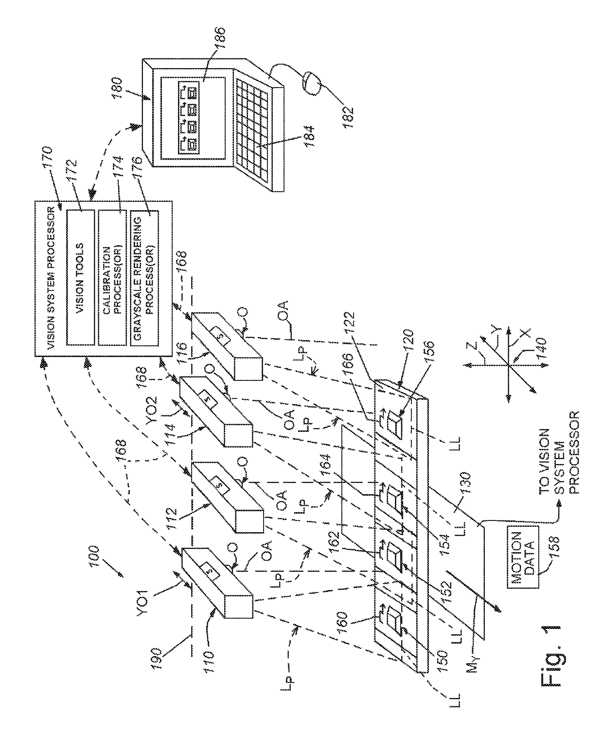
[0043]FIG. 1 details a vision system arrangement 100 that includes a plurality of (3D) displacement sensors 110, 112, 114 and 116. In this exemplary arrangement, four sensors are depicted. However at least two and greater than four sensors can be employed as the exemplary “plurality” as defined herein. The sensors 110, 112, 114, 116 can be arranged in a variety of orientations that are typically side-by-side with respect to each other as shown to define a widened (in the x-axis direction as defined below) field of view (FOV). The 3D sensors 110, 112, 114 and 116 in this exemplary arrangement are implemented as so-called laser profilers or laser displacement sensors that rely upon relative motion (arrow My) generated by a motion conveyance that acts along the y-axis direction between the sensor and the object 120 under inspection to provide a range image (also termed herein a “3D image”) of the object 120. As shown, in this embodiment, motion My is generated by the ...


PUM


Abstract

This invention provides a system and method for concurrently (i.e. non-serially) calibrating a plurality of 3D sensors to provide therefrom a single FOV in a vision system that allows for straightforward setup using a series of relatively straightforward steps that are supported by an intuitive graphical user interface (GUI). The system and method requires minimal input significant data about the imaged scene or calibration object used to calibrate the sensors, thereby effecting a substantially “automatic” calibration procedure. 3D features of a stable object, typically employing a plurality of 3D subobjects are first measured by one of the plurality of image sensors, and then the feature measurements are used in a calibration in which each of the 3D sensors images a discrete one of the subobjects, resolves features thereon and computes a common coordinate space between the plurality of 3D sensors. Laser displacement sensors and a conveyor / motion stage can be employed.

Description

FIELD OF THE INVENTION[0001]This invention relates to vision systems using a plurality of three-dimensional (3D) vision system cameras, and more particularly to calibration of a plurality vision system cameras employed to image objects in relative motion.BACKGROUND OF THE INVENTION[0002]In manufacturing and assembly processes, it is often desirable to analyze an object surface to determine the nature of features and / or irregularities. The displacement (or “profile”) of the object surface can be determined using a machine vision system (also termed herein “vision system”) in the form of a laser displacement sensor (also termed a laser beam “profiler”). A laser displacement sensor captures and determines the (three dimensional) profile of a scanned object surface using a planar curtain or “fan” of a laser beam at a particular plane transverse to the beam propagation path. In a conventional arrangement, a vision system camera assembly is oriented to view the plane of the beam from outs...

Claims


Application Information

Patent Timeline
IPC IPC(8): G06T7/80H04N13/246H04N17/00G06T7/20G06T7/00G06K9/52G06T7/60
CPCH04N17/002G06K9/52G06T7/60H04N13/246G06T7/20G06T7/0042G06T2200/04G06T7/85G06T2207/10016G06T2207/10152G06T2207/30108G06T2207/30204H04N23/60H04N23/50G06T7/73
Inventor WANG, RUIBINGWALLACK, AARON S.MICHAEL, DAVID J.ZHU, HONGWEI
Owner COGNEX CORP
Learn More