
Apparatus and method for presuming abnormality occurrence for telescopic cover

a technology of telescopic cover and abnormality, which is applied in the field of apparatus and a method for presuming abnormality occurrence of telescopic cover, can solve the problems of inability to easily perform state recognition and replacement of cushioning parts, abrasion or breakage of cushioning parts, etc., and achieves stably maintained production, improved operating rate, and prevent subsequent breakage of the very plate cover

Active Publication Date: 2020-09-01
FANUC LTD
View PDF18 Cites 2 Cited by
  • Summary
  • Abstract
  • Description
  • Claims
  • Application Information

AI Technical Summary

Benefits of technology

[0020]The present invention can provide the abnormality occurrence presumption apparatus and the abnormality occurrence presumption method which allow the occurrence of an abnormality such as a fracture in a telescopic cover or abrasion / breakage of a cushioning part to be predicted. By introducing the abnormality occurrence presumption apparatus according to the present invention, it is possible for a user of a machine tool to recognize that the very telescopic cover or the cushioning part attached to the telescopic cover is abraded or broken and a plate cover needs repair and maintenance without performing regular checking and part replacement. This allows planned preventive maintenance to be performed before the machine suddenly breaks down / stops and leads to an improved operating rate and stably maintained production. In addition, since only a consumable item such as the cushioning part can be replaced when the cushioning part is abraded or broken, it is possible to prevent subsequent breakage of the very plate cover. This leads to reduced maintenance cost and time.

Problems solved by technology

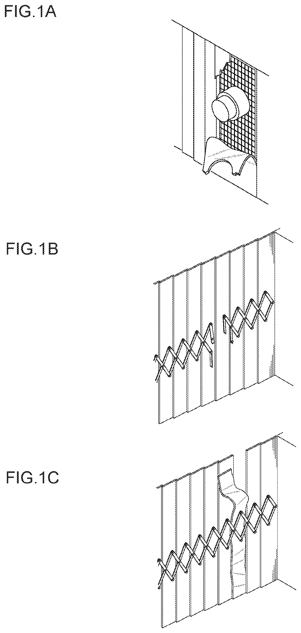
Such breakage is caused by various factors such as, e.g., aging degradation of each of parts induced by fatigue or wear, a loosened or detached fixation screw, deformation caused by falling of a workpiece, and an erroneous operation.
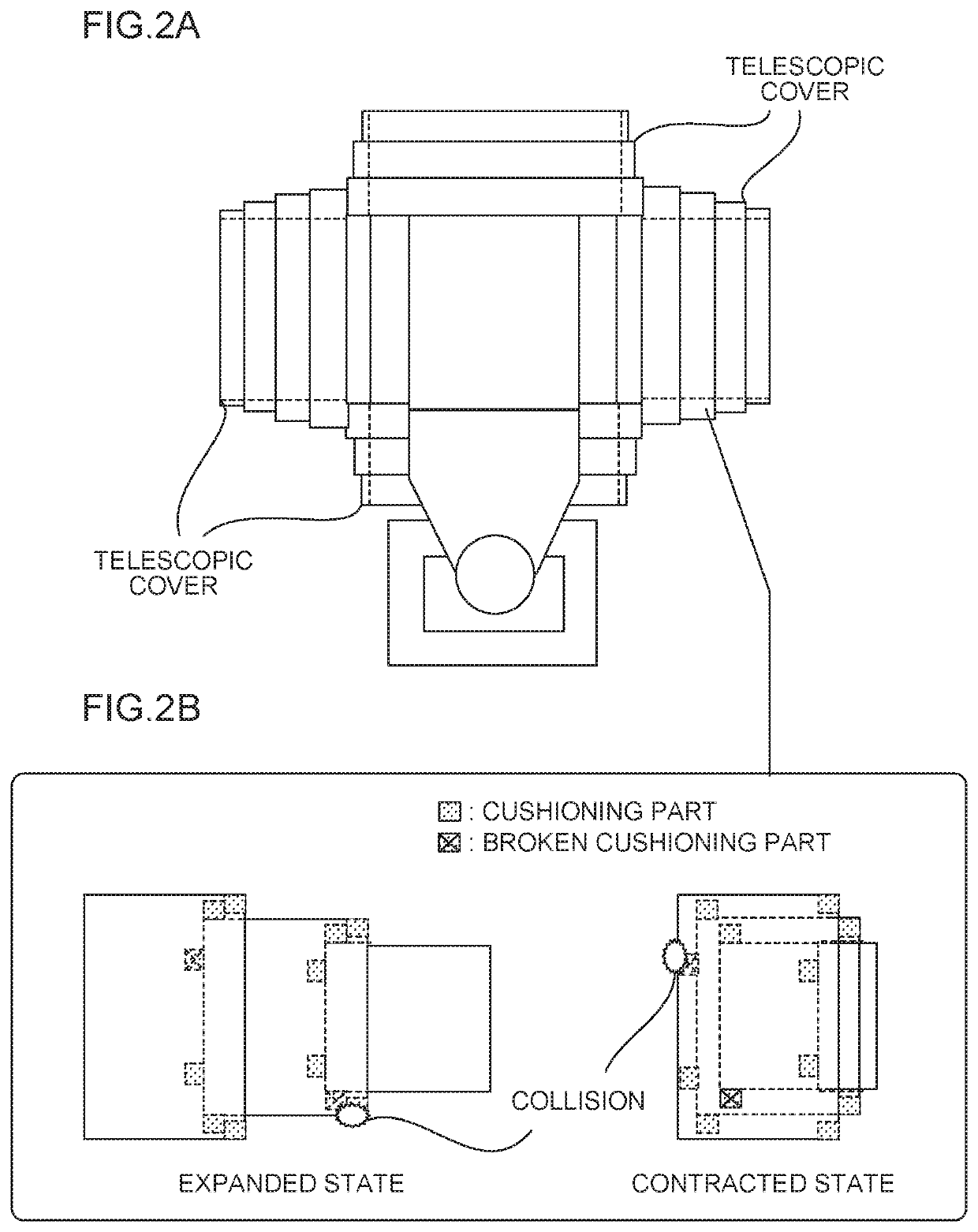
Since the cushioning parts of the telescopic cover are constantly subjected to impact while the movable part of the telescopic cover is operating, the cushioning parts undergo abrasion or breakage.
However, due to limitations concerning a usage environment and the structure of the plate covers, the cushioning members are typically attached to the inner portions of the plate covers, as described above.
While the breakage and abrasion of the cushioning members can be avoided through regular checking and part replacement, the state recognition and replacement of the cushioning parts necessitates the removal of the plate covers or the like, and cannot be easily performed.
Consequently, some users may fail to perform a checking operation and continue to use the cushioning parts.
In such a case, not only the cushioning parts are abraded or broken, but also the main bodies of the plate covers may be broken.
The occurrence of such breakage not only disturbs the safe and stable operation of the machine tool, but also creates the need for significant time and cost of repairs.
According to the technique, a light emitter and a light receiver are provided in the telescopic cover and, when the light generated from the light emitter is blocked by a plate body and is not received by the light receiver, it is determined that an abnormality has occurred.
However, the technique described above allows only an abnormality such as a change in the preliminarily assumed form of a preliminarily assumed member to be detected.
It is impossible to obtain the effect of recognizing an event leading to the occurrence of an abnormality and predicting a situation where an abnormality may occur.

Method used


Image

  • Apparatus and method for presuming abnormality occurrence for telescopic cover
  • Apparatus and method for presuming abnormality occurrence for telescopic cover
  • Apparatus and method for presuming abnormality occurrence for telescopic cover

Examples


embodiment

2. Embodiment

[0054]FIG. 6 is a block diagram showing a schematic configuration of an abnormality occurrence presumption apparatus 1 for a telescopic cover in an embodiment of the present invention.

[0055]Typically, the abnormality occurrence presumption apparatus 1 can be embodied as an information processing apparatus such as a computer connected to a sensor 2 described later via a communication line, a signal line, or the like. The abnormality occurrence presumption apparatus 1 includes a supervised learning machine 10 (dotted line frame in the drawing), a physical quantity acquisition unit 20, a feature amount extraction unit 30, and a presumption result output unit 40.

[0056]The sensor 2 includes various sensors such as a vibration sensor or a sound sensor attached to a machining tool or the telescopic cover and a measuring instrument (not shown) connected to any of the foregoing various sensors, a numerical controller capable of acquiring the position, speed, acceleration or load...


PUM

PropertyMeasurementUnit
physical quantityaaaaaaaaaa
physicalaaaaaaaaaa
currentaaaaaaaaaa

Abstract

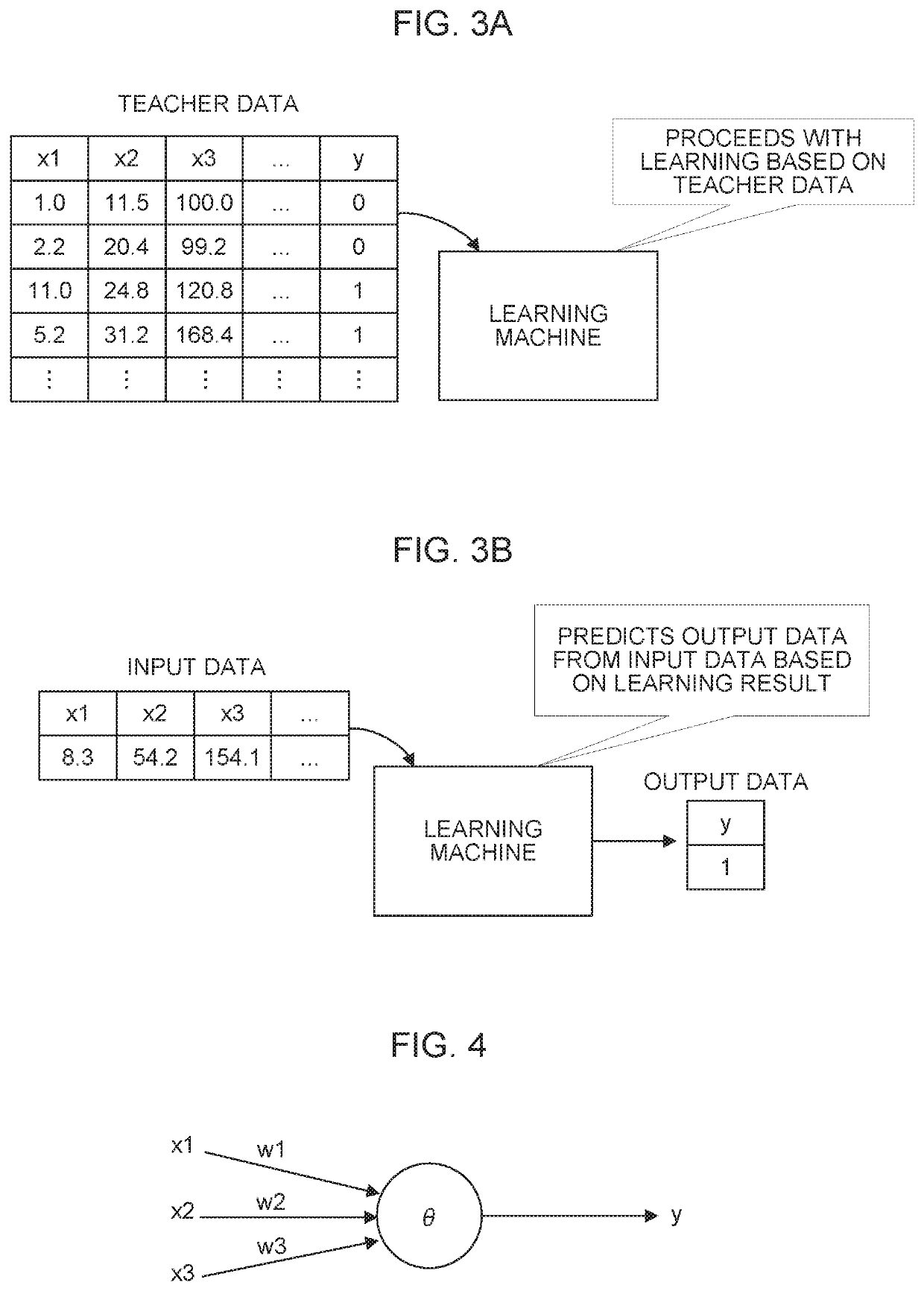
An abnormality occurrence presumption apparatus which presumes the occurrence of an abnormality in a telescopic cover attached to a machine tool performs supervised learning on the basis of a feature amount extracted from a physical quantity acquired during an operation of the machine tool and information related to an abnormality occurring in the telescopic cover, and stores the result of the learning. The abnormality occurrence presumption apparatus presumes an abnormality that may occur in the telescopic cover during the operation of the machine tool on the basis of the result of the learning and the feature amount extracted from the physical quantity.

Description

RELATED APPLICATIONS[0001]The present application claims priority to Japanese Patent Application No. 2016-227720 filed on Nov. 24, 2016, and Japanese Patent Application No. 2017-174459 filed on Sep. 12, 2017, the disclosures of which are hereby incorporated by reference herein in their entirety.BACKGROUND OF THE INVENTION1. Field of the Invention[0002]The present invention relates to an apparatus and a method for presuming abnormality occurrence for a telescopic cover, and particularly to a technique which predicts the occurrence of an abnormality such as a fracture in a telescopic cover and abrasion or breakage of cushion parts.2. Description of the Related Art[0003]A telescopic cover is intended to protect the internal mechanism of a machine tool (device) from chips and a cutting fluid which are generated when the machine tool performs machining. The telescopic cover has a structure which drives a multi-stage metallic cover using a telescopic member such as a pantograph to open / cl...

Claims


Application Information

Patent Timeline
Patent Type & Authority Patents(United States)
IPC IPC(8): G01N29/04G01N29/44G01N29/14G01N27/20
CPCG01N27/20G01N29/04G01N29/14G01N29/4472G01N29/4418G01N29/4481B23Q11/0816G06N3/084G06F30/17G06F2119/04G06F30/20
Inventor KUROKAMI, NOBORUSATO, NAOKI
Owner FANUC LTD
Learn More