System and method for using mobile device of zone and correlated motion detection

a mobile device and motion detection technology, applied in the field of system and method for using mobile device of zone and correlated motion detection, can solve the problems of improper selection of camera type, potential deadzone, improper positioning of cameras, etc., and achieve excellent image data processing resources, better interpret image data, and easy grasp of context

Active Publication Date: 2020-09-01
JOHNSON CONTROLS TYCO IP HLDG LLP
View PDF149 Cites 0 Cited by
  • Summary
  • Abstract
  • Description
  • Claims
  • Application Information

AI Technical Summary

Benefits of technology

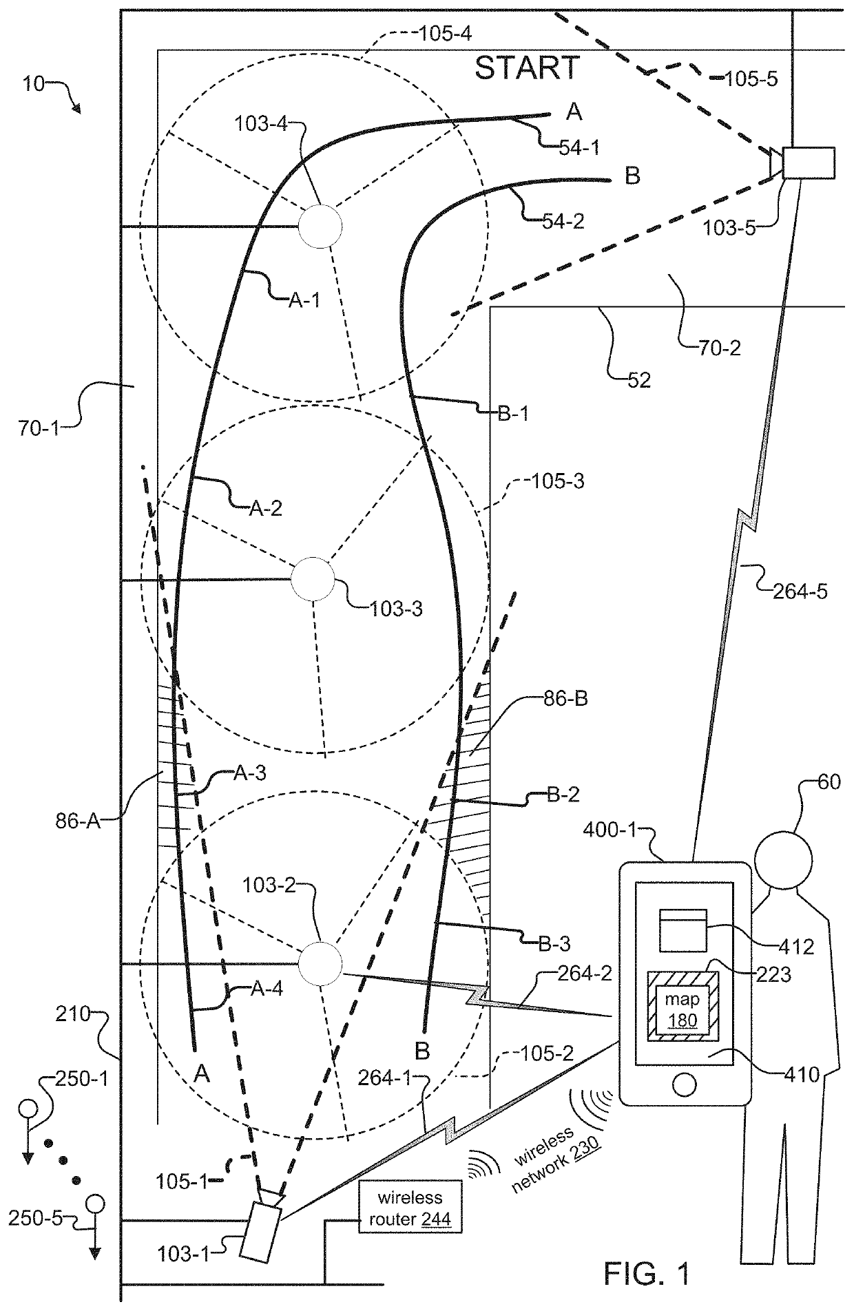
[0018]It would also be beneficial to infer the presence of deadzones from image data captured by the surveillance cameras. Such a capability enables operators to better understand image data from existing surveillance cameras installations and to better interpret that image data.
[0020]Finally, it would also be beneficial to infer overlap among fields of view of surveillance cameras from image data captured by the surveillance cameras. Such a capability could allow system operators to better interpret image data from different cameras. Moreover, the analytics systems could use this information to present image data to operators in a way that is easier to grasp context.

Problems solved by technology

A common problem when installing surveillance cameras is the potential for deadzones.
These deadzones might result from improper positioning of the cameras and / or improper selection of the type of cameras installed.
On the other hand, the existence of deadzones might simply be the consequence of a limited budget and the fact that deploying enough cameras to achieve total coverage is not feasible.
At the same time, deadzones can result when there are obstructions present in the scenes of the cameras.
Obstructions within the scenes such as pylons, bookcases, cubicle walls, file cabinets, and stairwells can cause areas behind the obstructions to be hidden from view.

Method used


Image

  • System and method for using mobile device of zone and correlated motion detection
  • System and method for using mobile device of zone and correlated motion detection
  • System and method for using mobile device of zone and correlated motion detection

Examples


Embodiment Construction

[0041]The invention now will be described more fully hereinafter with reference to the accompanying drawings, in which illustrative embodiments of the invention are shown. This invention may, however, be embodied in many different forms and should not be construed as limited to the embodiments set forth herein; rather, these embodiments are provided so that this disclosure will be thorough and complete, and will fully convey the scope of the invention to those skilled in the art.

[0042]As used herein, the term “and / or” includes any and all combinations of one or more of the associated listed items. Further, the singular forms including the articles “a”, “an” and “the” are intended to include the plural forms as well, unless expressly stated otherwise. It will be further understood that the terms: includes, comprises, including and / or comprising, when used in this specification, specify the presence of stated features, integers, steps, operations, elements, and / or components, but do n...


PUM


Abstract

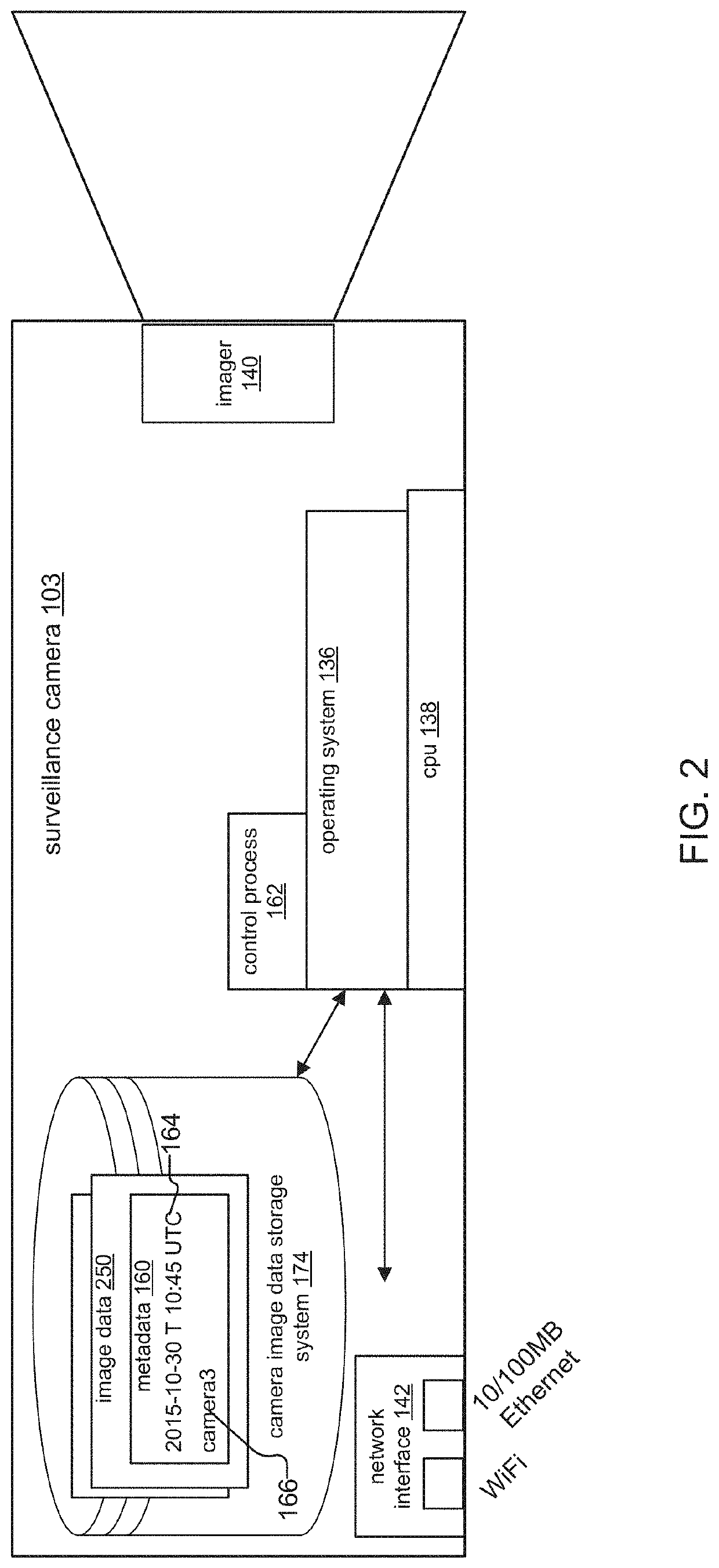
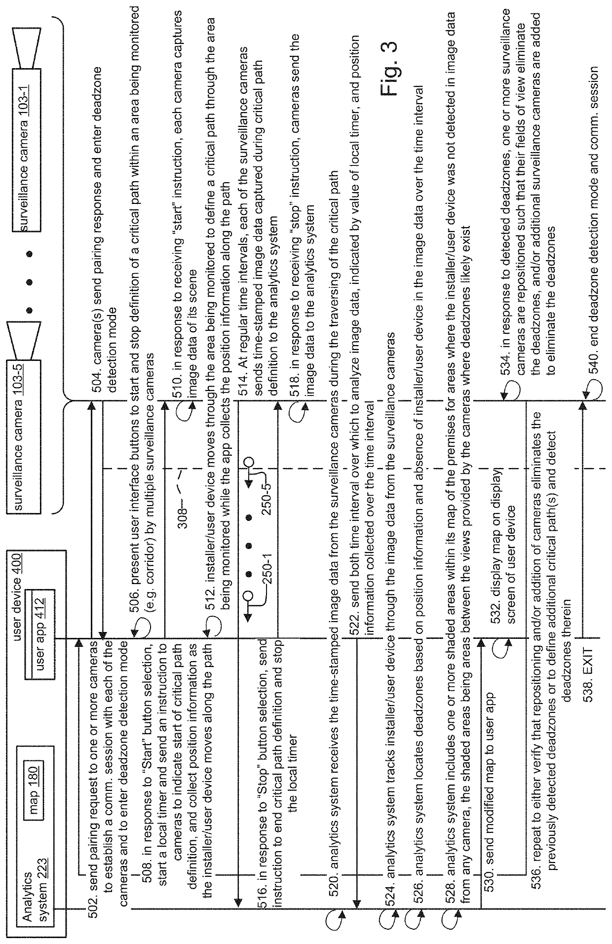
A system and method for determining relationships between fields of views of surveillance cameras is disclosed. In the system, a user device such as a mobile phone receives image data from the cameras, and an analytics system of the user device analyzes the image data to determine the relationships between the fields of views of the surveillance cameras. The relationships include overlap among fields of view of at least two of the cameras and deadzones, where deadzones are areas monitored by the cameras that are not included within any of the fields of view of any of the cameras. In a preferred embodiment, the surveillance cameras capture image data of a scene while an installer holding the user device walks one or more critical paths through the scene. The user device then analyzes image data from the cameras during the critical path definition to determine any overlap and / or deadzones.

Description

RELATED APPLICATIONS[0001]This application is related to:[0002]U.S. application Ser. No. 15 / 076,701 filed on Mar. 22, 2016, entitled “Method and system for surveillance camera arbitration of uplink consumption,” now U.S. Patent Publication No.: 2017 / 0278368 A1;[0003]U.S. application Ser. No. 15 / 076,703 filed on Mar. 22, 2016, entitled “Method and system for pooled local storage by surveillance cameras,” now U.S. Patent Publication No.: 2017 / 0280102 A1;[0004]U.S. application Ser. No. 15 / 076,704 filed on Mar. 22, 2016, entitled “System and method for designating surveillance camera regions of interest,” now U.S. Patent Publication No.: 2017 / 0277967 A1;[0005]U.S. application Ser. No. 15 / 076,705 filed on Mar. 22, 2016, entitled “System and method for deadzone detection in surveillance camera network,” now U.S. Patent Publication No.: 2017 / 0278366 A1;[0006]U.S. application Ser. No. 15 / 076,706 filed on Mar. 22, 2016, entitled “System and method for overlap detection in surveillance camera...

Claims


Application Information

Patent Timeline
Patent Type & Authority Patents(United States)
IPC IPC(8): H04N7/18H04N5/232
CPCH04N7/181H04N5/23206H04N5/23296H04N5/23222H04N23/661H04N23/64H04N23/69
Inventor BURKE, ANTHONYBIRKEL, PETER JOSEPH
Owner JOHNSON CONTROLS TYCO IP HLDG LLP
Why Eureka
Try Eureka