

Robot surveillance system and method
a technology of robots and surveillance systems, applied in the direction of vehicle position/course/altitude control, process and machine control, instruments, etc., can solve the problems of difficult control, limited endurance, and limited range of aerial video systems, so as to improve image- and/or terrain data, manufacturing at relatively low cost, and less concern for maneuverability and controllability
- Summary
- Abstract
- Description
- Claims
- Application Information
AI Technical Summary
Benefits of technology
Problems solved by technology
Method used
Image

Examples
Embodiment Construction
[0032]Aside from the preferred embodiment or embodiments disclosed below, this invention is capable of other embodiments and of being practiced or being carried out in various ways. Thus, it is to be understood that the invention is not limited in its application to the details of construction and the arrangements of components set forth in the following description or illustrated in the drawings. If only one embodiment is described herein, the claims hereof are not to be limited to that embodiment. Moreover, the claims hereof are not to be read restrictively unless there is clear and convincing evidence manifesting a certain exclusion, restriction, or disclaimer.
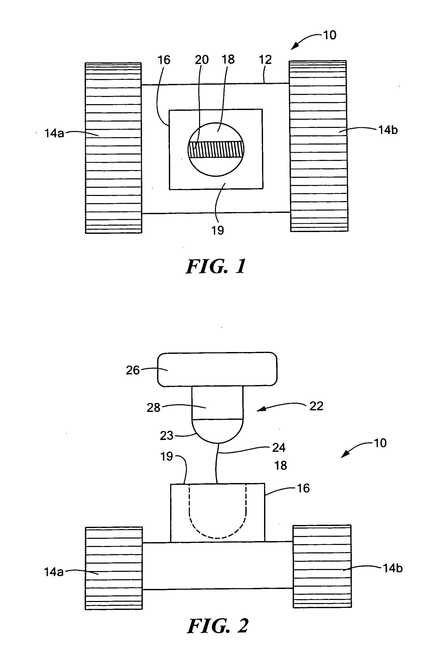
[0033]FIGS. 1-2 depict robot 10 with chassis 12 and a drive subsystem including tracks 14a and 14b as disclosed in U.S. Patent Application Publication No. 2009 / 0071281. Wheels are also possible as disclosed in U.S. Patent Application Publication No. 2009 / 0266628. Still other robots include legs, flippers, and the like.
[0034...
PUM
 Abstract
Description
Claims
Application Information