Planetary gear device and vehicle wheel drive device

a technology of planetary gear and vehicle wheel, which is applied in the direction of gearing details, gearing, transportation and packaging, etc., can solve the problems of lubricating oil sealed inside the gear device leaking to the outside of the gear device, and achieve the effect of preventing the reduction of torque transmission efficiency, reducing friction loss, and reducing torque transmission efficiency

Active Publication Date: 2020-09-08
MITSUBISHI ELECTRIC CORP
View PDF8 Cites 0 Cited by
  • Summary
  • Abstract
  • Description
  • Claims
  • Application Information

AI Technical Summary

Benefits of technology

[0013]The planetary gear device of the present disclosure employs bearings having large gaps for railway vehicles. The planetary gear device eliminates a friction loss that is a factor reducing a torque transmission efficiency by the friction force of a sliding contact portion by only using the labyrinth seals that, due to bearing clearance, allow movement of the shaft in the radial direction. Therefore, reduction of the torque transmission efficiency can be prevented.

Problems solved by technology

A gap exists between opposing surfaces of a fixed portion supporting the gear device and an input rotation portion input and / or an output rotation portion input from / output to the outside due to the relative movement of the opposing surfaces, and a lubricating oil sealed inside the gear device may leak to the outside of the gear device.

Method used


Image

  • Planetary gear device and vehicle wheel drive device
  • Planetary gear device and vehicle wheel drive device
  • Planetary gear device and vehicle wheel drive device

Examples


embodiment 1

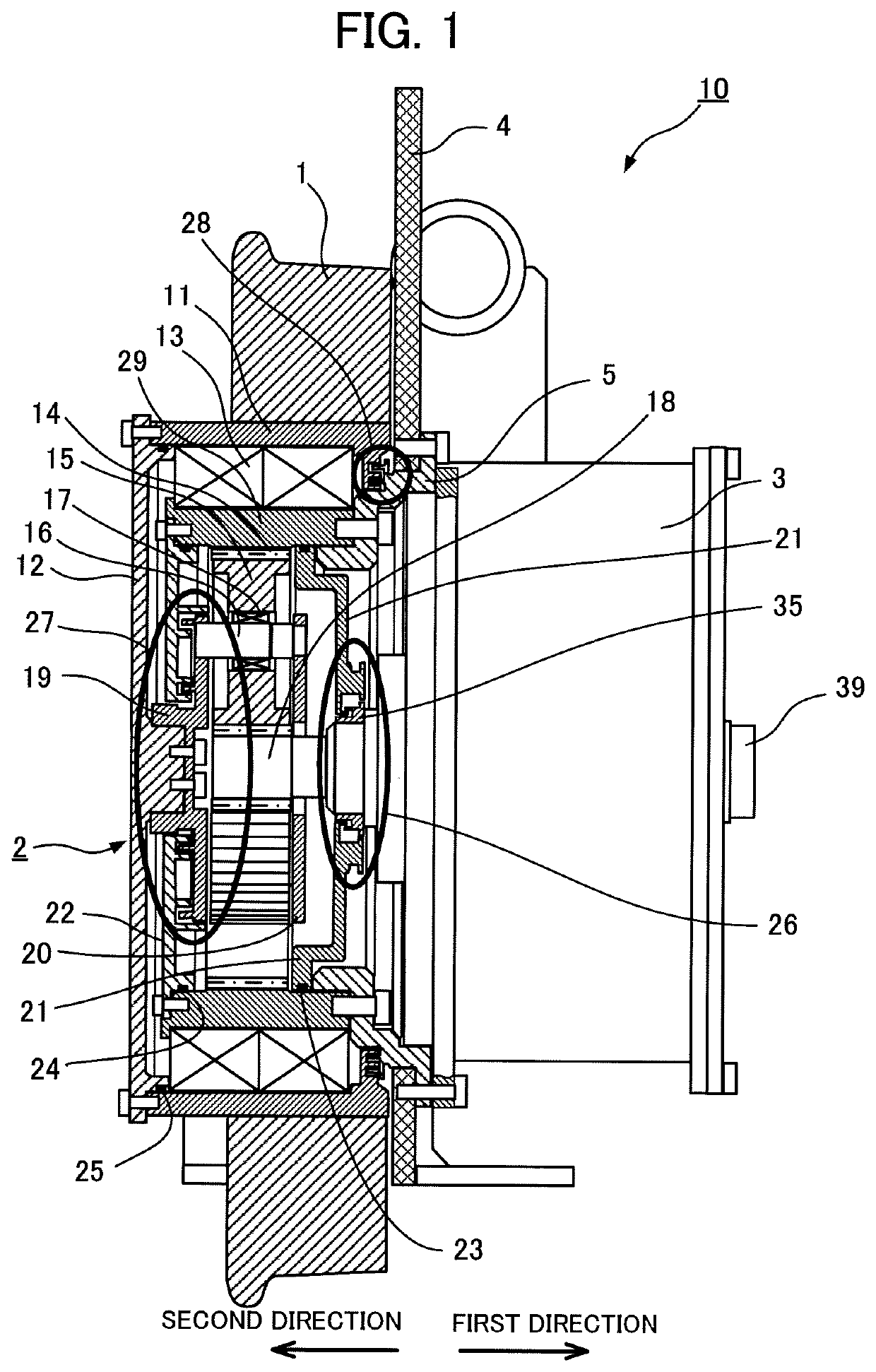
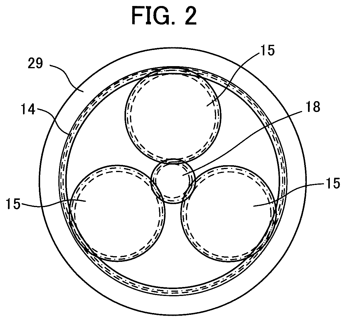
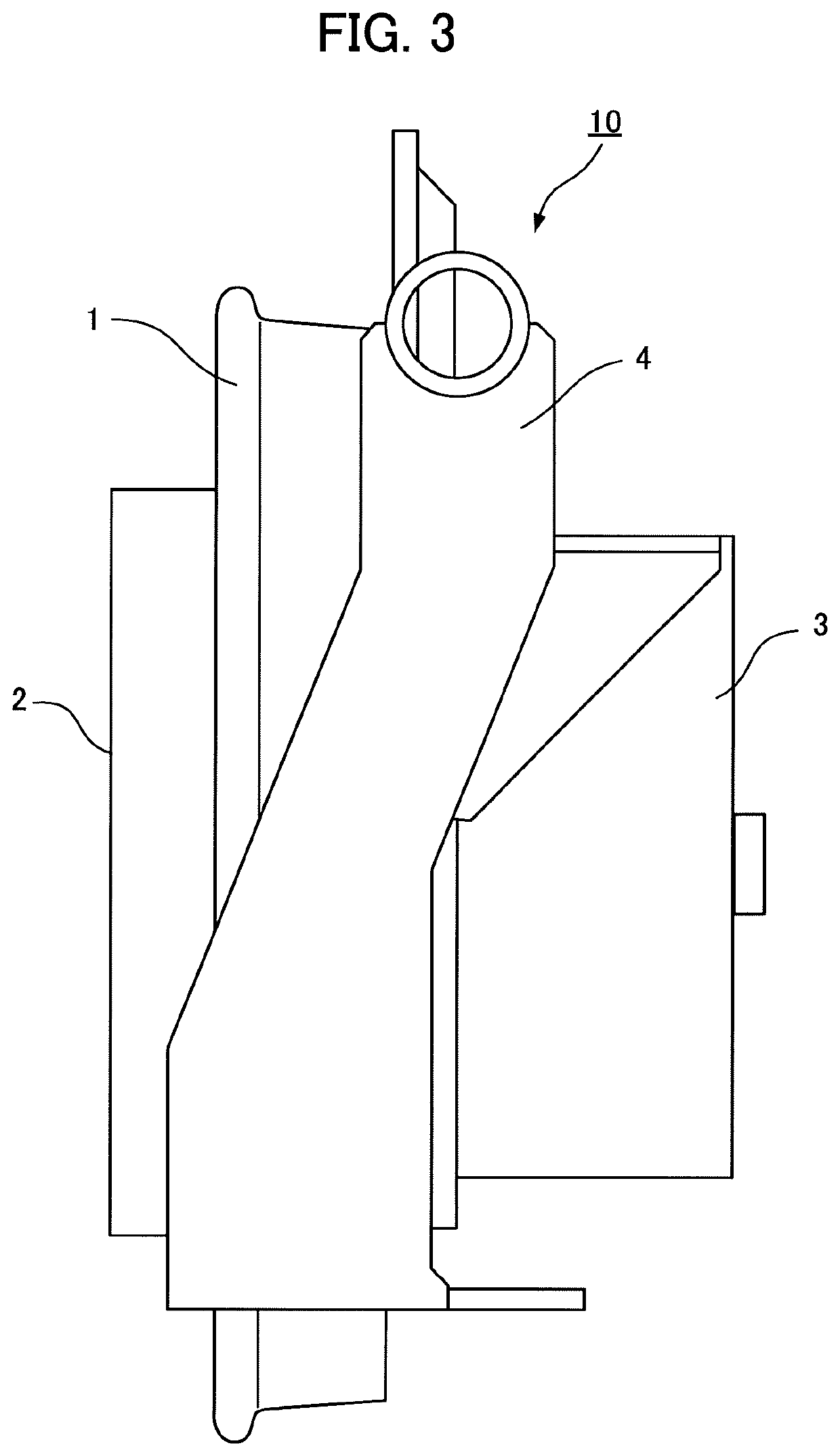
[0026]FIG. 1 is a cross-sectional view illustrating an internal configuration of a vehicle wheel drive device according to Embodiment 1 of the present disclosure. A vehicle wheel drive device 10 according to Embodiment 1 uses a planetary gear device 2 in which a drive shaft 39 coupled to a sun gear 18 is an input shaft and an output shaft outer cylinder 11 is an output shaft. Here, viewing from an internal gear 14 of the planetary gear device 2 in the axial direction, the direction of the drive shaft 39 is referred to as a first direction, and the direction of a planetary carrier 19 opposite to the drive shaft 39 is referred to as a second direction.

[0027]In the planetary gear device 2 according to Embodiment 1, an annular slinger 35 fitted in the drive shaft 39 coupled to the sun gear 18 is arranged on the first direction side of the planetary gear device 2. An annular drive shaft seal plate 21, in which the drive shaft 39 is inserted and arranged apart from the slinger 35 to form ...

embodiment 2

[0058]FIG. 8 is a cross-sectional view of a first labyrinth seal of a planetary gear device according to Embodiment 2 of the present disclosure. In Embodiment 2, a shape of a portion, in which a drive shaft seal plate 61 and a slinger 65 of the first labyrinth seal 26 oppose each other, is changed. The other configurations are the same as those of the planetary gear device 2 according to Embodiment 1.

[0059]The annular protrusion 31 of the annular drive shaft seal plate 61 is inter-convoluted with the annular groove 37 of the slinger 65 without any contact in a manner similar to that of Embodiment 1. In addition, an inner circumferential protrusion 64 (a first inner circumferential protrusion) of the drive shaft seal plate 61 faces an outer circumferential protrusion 67 (a first outer circumferential protrusion) of the slinger 65 in the radial direction to form a gap.

[0060]In Embodiment 2, an outer circumferential groove 68 that is a first outer circumferential groove recessed inward...

embodiment 3

[0063]FIG. 9 is a cross-sectional view of a first labyrinth seal of a planetary gear device according to Embodiment 3 of the present disclosure. In Embodiment 3, the shapes of the portions where a drive shaft seal plate 71 faces an slinger 76 are changed in the first labyrinth seal 26, and a rear seal disc 78 is provided on the first direction side of the slinger 76. The other configurations are the same as those of the planetary gear device 2 according to Embodiment 1.

[0064]Similar to Embodiment 1, the annular protrusion 31 of the annular drive shaft seal plate 71 is fitted into the annular groove 37 of the slinger 76 forming a gap. An annular groove 72 (a first annular groove) recessed in the second direction over the circumference of the shaft is formed on the outer circumferential side of the annular protrusion 31 in the drive shaft seal plate 71, and the annular protrusion 36 of the slinger 76 is fitted in the annular groove 72 forming a gap. An inner circumferential protrusion...


PUM


Abstract

A first labyrinth seal includes: a drive shaft side annular protrusion that is formed on one of the slinger and the drive shaft seal plate and that protrudes over the circumference of the drive shaft; and a drive shaft side annular groove that is formed on the other of the slinger and the drive shaft seal plate and that recedes over the circumference of the shaft. A second labyrinth seal includes: a carrier-side annular protrusion that is formed on one of the carrier seal plate and the planetary carrier and that protrudes over the circumference of the shaft of the planetary carrier; and a carrier-side annular groove that is formed on the other of the carrier seal plate and the planetary carrier and that recedes over the circumference of the shaft.

Description

TECHNICAL FIELD[0001]The present disclosure relates to a planetary gear device and a vehicle wheel drive device using the planetary gear device.BACKGROUND ART[0002]A planetary gear device including a planetary gear, in which a gear center shaft engages with a cylindrical internal gear and revolves, and a sun gear at the center of the planetary gear engaging with the planetary gear, is small in size and lightweight and is a gear device that can increase a reduction gear ratio. The planetary gear devices are used for various applications such as speed reduction devices, transmissions and pumps.[0003]In the planetary gear device, lubrication is essential for bearings supporting the planetary gears and rotating members, and teeth surfaces of engaging gears. The bearings and engaging gear surfaces of the planetary gear device are generally lubricated with lubricating oil. A gap exists between opposing surfaces of a fixed portion supporting the gear device and an input rotation portion in...

Claims


Application Information

Patent Timeline
Patent Type & Authority Patents(United States)
IPC IPC(8): F16H57/08F16H1/36B60B27/00F16C33/78F16H57/04B60K7/00
CPCF16H57/0471F16C33/7816F16H57/0486B60B27/0021F16H57/082F16H57/0457B60B27/0047F16H1/36F16H57/0479B60B2900/114B60K2007/0092B60B2380/73B60B2900/561B60K7/0007B60B2900/111B60B2900/5118F16H57/04F16H57/029F16J15/4476
Inventor HASHIMOTO, MICHINORITERASAWA, HIDEO
Owner MITSUBISHI ELECTRIC CORP
Why Eureka
Try Eureka