Clutch actuator and method for controlling a clutch actuator

a technology of clutch actuator and clutch actuator, which is applied in the direction of mechanical actuated clutches, magnetically actuated clutches, couplings, etc., can solve the problems of increasing wear in the long term, and achieve the effect of high accuracy

Active Publication Date: 2022-09-06
FTE AUTOMOTIVE GMBH & CO KG
View PDF22 Cites 0 Cited by
  • Summary
  • Abstract
  • Description
  • Claims
  • Application Information

AI Technical Summary

Benefits of technology

[0005]It is the object of the invention to provide a clutch actuator which allows precise actuation of the clutch, while wear adjustment and relief of the load on the pushrod in the coupled mode should be possible at the same time.
[0008]As sensors, it is possible, in particular, to use Hall-effect sensors or GMR sensors, which make it possible to detect the desired movement with a very high accuracy.
[0009]The guide component is preferably provided with a permanent magnet, thus enabling the stroke of the guide component and hence of the tappet to be detected very precisely by means of the stroke sensor.
[0014]According to one embodiment of the invention, it is envisaged that the drive has an electric motor with a rotor which has a rotor shaft rotatably mounted in the housing, and that the spindle nut is coupled directly to the rotor shaft. By means of this embodiment, frictional losses between the electric motor and the spindle nut, of the kind which would otherwise occur in a gear mechanism, are eliminated.
[0015]According to an alternative embodiment, it is envisaged that the pushrod is a rack, in that the drive has a pinion, a gear mechanism and a drive motor, and that the rotation angle sensor is associated with the pinion, with one of the components of the gear mechanism or with a rotor shaft of the electric motor. Particularly if the rotation angle sensor is associated with the rotor shaft of the electric motor, the rotational position of the drive can be detected with high accuracy.

Problems solved by technology

Otherwise, any vibration in the clutch would be transferred continuously to the clutch actuator and would result in increased wear in the long term.

Method used


Image

  • Clutch actuator and method for controlling a clutch actuator
  • Clutch actuator and method for controlling a clutch actuator
  • Clutch actuator and method for controlling a clutch actuator

Examples


Embodiment Construction

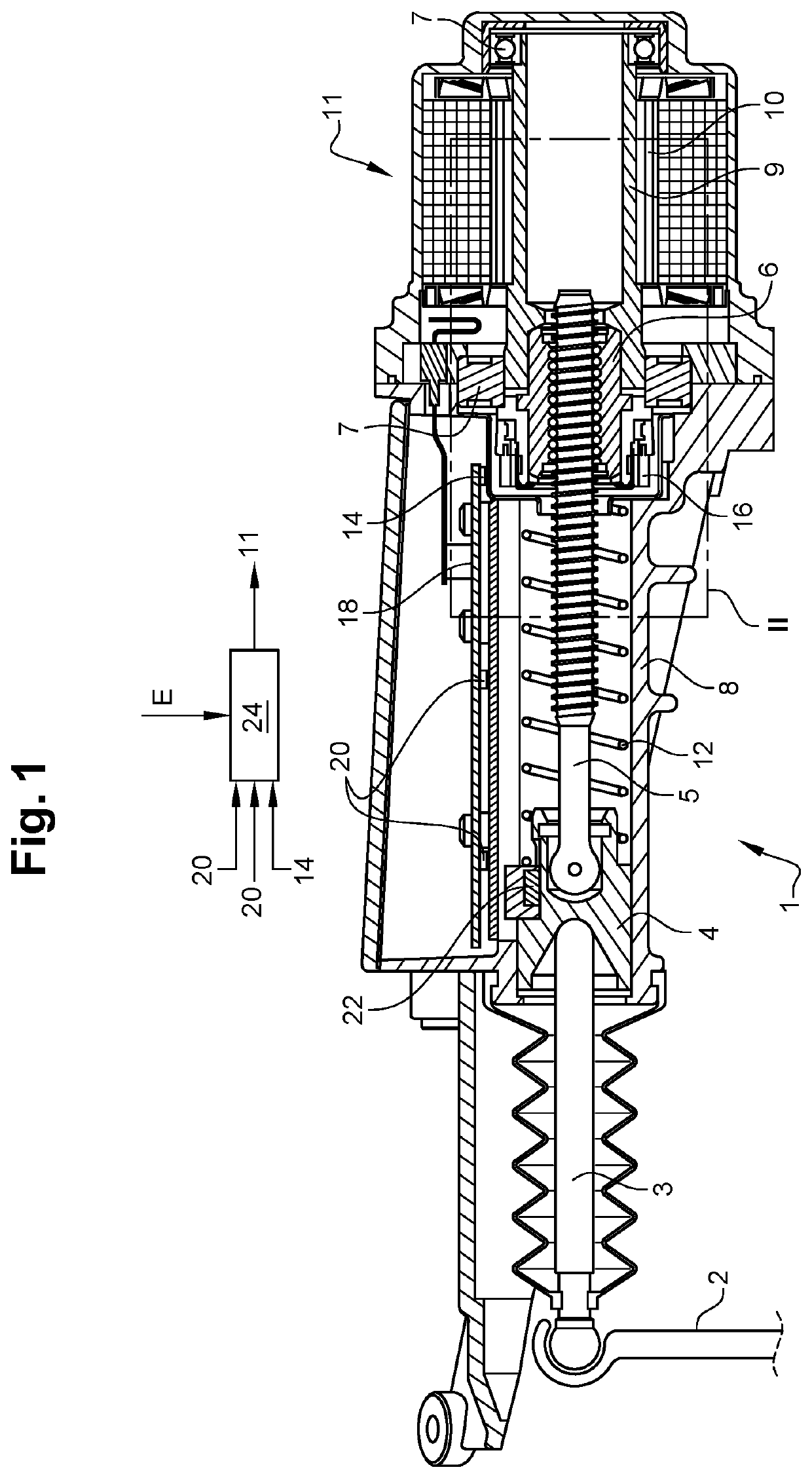
[0022]FIG. 1 shows a clutch actuator 1 which serves to adjust a release lever 2 of a clutch (not shown here) in order to disengage and re-engage the clutch. The clutch can be, in particular, a friction clutch in the power flow between a drive motor and a transmission of a heavy goods vehicle.

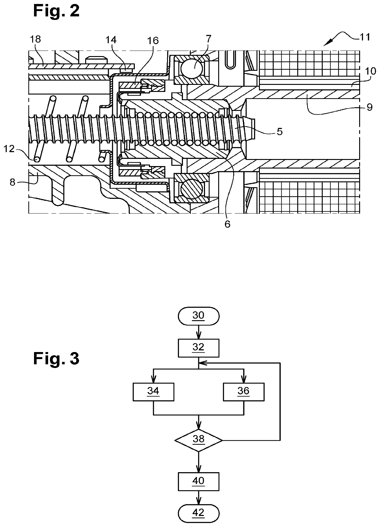
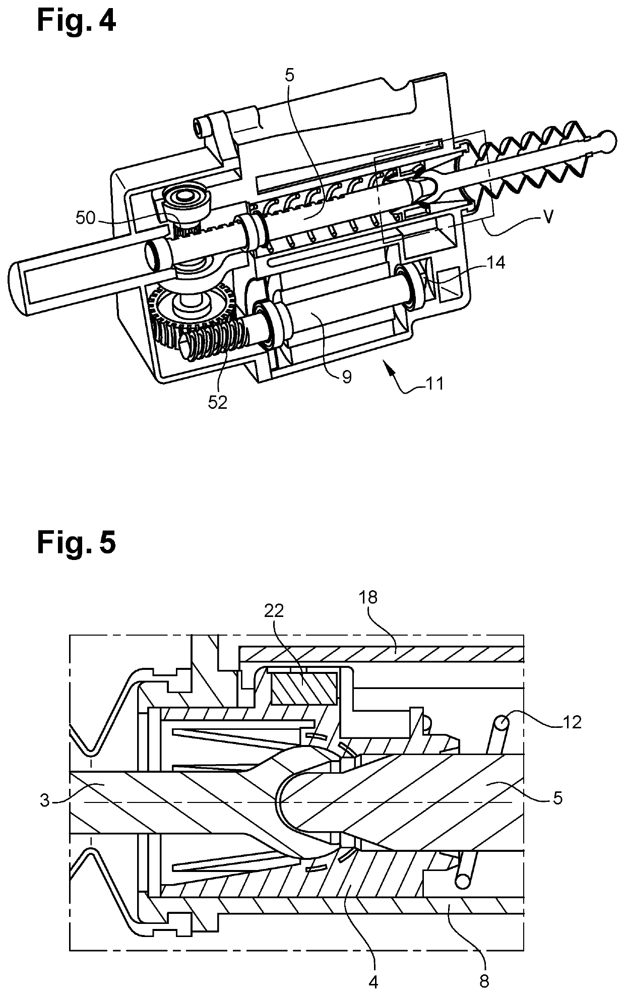
[0023]Engaging on the release lever 2 is a tappet 3, which is supported on a guide component 4. A pushrod 5, which is here embodied as a spindle, is supported on the opposite end of the guide component 4. That end of the spindle 5 which faces away from the guide component is accommodated in a spindle nut 6, which is mounted rotatably in a housing 8 of the clutch actuator 1 by means of rolling bearings 7.

[0024]In the embodiment shown, the spindle nut 6 is mounted for conjoint rotation on a rotor shaft 9, which is part of a rotor 10 of an electric motor 11. By means of the electric motor 11, the spindle nut 6 can be rotated in one or the other direction.

[0025]Provided within the housing 8 is a pre...


PUM


Abstract

A clutch actuator for actuating a clutch in the drive train of a motor vehicle, having a housing, a drive, a pushrod, which can be adjusted in an axial direction by the drive, a tappet, which is coupled to the pushrod, and a guide component which is accommodated movably in the housing and receives that end of the tappet which faces the pushrod. At least one stroke sensor, which is associated with the guide component, and a rotation angle sensor, which is associated with the drive, are provided. Embodiments relate to an assembly having a clutch actuator of this kind and a controller, the controller is set up and designed to determine the start of the release stroke of a clutch actuated by the clutch actuator from a comparison of the signal of the stroke sensor and the signal of the rotation angle sensor.

Description

FIELD[0001]The invention relates to a clutch actuator for actuating a clutch in the drive train of a motor vehicle, having a housing, a drive, a pushrod, which can be adjusted in an axial direction by the drive, a tappet, which is coupled to the pushrod, and a guide component, which is accommodated movably in the housing and receives that end of the tappet which faces the pushrod.BACKGROUND[0002]A clutch actuator of this kind can be used to open and close a friction clutch in the drive train of a motor vehicle, in particular of a heavy goods vehicle. Here, the tappet generally acts on a release bearing of the clutch via a release lever. As a drive, it is possible, for example, to use an electric motor, the rotation of which is converted into a stroke of the pushrod and hence of the tappet by a suitable mechanism.[0003]Above and beyond the actuation of the clutch, the clutch actuator is also used for automatic wear adjustment. This is accomplished by the fact that, after the clutch h...

Claims


Application Information

Patent Timeline
Patent Type & Authority Patents(United States)
IPC IPC(8): F16D27/01F16D28/00F16D48/06F16D121/24F16D125/24
CPCF16D27/01F16D28/00F16D48/064F16D2121/24F16D2125/24F16D2500/1023F16D2500/3021F16D2500/3026F16D23/12F16D48/06F16D2121/14F16D2300/18F16D2023/123
Inventor OSTROHOV, DIMITRISTAWINOGA, PAUL
Owner FTE AUTOMOTIVE GMBH & CO KG
Why Eureka
Try Eureka