Turbomachine which can be operated both as hydraulic motor and as pump

a technology of hydraulic motor and pump, which is applied in the direction of intermeshing engagement type engines, rotary piston engines, rotary or oscillating piston engines, etc., can solve the problems of reduced efficiency, high pressure-dependent and rotational direction-dependent axial forces, and high pressure-dependent and rotational direction-dependent friction losses, so as to achieve high starting torque, eliminate friction losses, and improve efficiency

Active Publication Date: 2021-11-16
BAUM REGINALD
View PDF16 Cites 0 Cited by
  • Summary
  • Abstract
  • Description
  • Claims
  • Application Information

AI Technical Summary

Benefits of technology

[0011]The turbomachine is preferably to be capable of being implemented using the two-tube principle without a separate leakage outflow, and can be equipped with a control device and an associated drive, with the result that it maintains its high efficiency even at high pressures. The control device is to make it possible to implement a freewheeling function, a braking function, a blocking function, a soft start, linearization of the characteristic curves and adaptation of characteristic curves to specific load requirements within an adjustment range.
[0013]It was quite surprising for a person skilled in the art that with the turbomachine according to the invention all the abovementioned disadvantages no longer occurred. The significant and decisive advantage of the proposed turbomachine is that it is very functionally reliable in all four quadrants, has the same properties with right-hand rotation and left-hand rotation and achieves a significantly higher efficiency and very high starting torques by eliminating friction losses.

Problems solved by technology

The disadvantage here is that very high pressure-dependent and rotational-direction-dependent axial forces occur in these machines.
These forces give rise to very high pressure-dependent and rotational-direction-dependent friction losses.
As a result, these machines are non-linear, have different properties during right-hand rotation and left-hand rotation and have reduced efficiency.
Further disadvantages of these solutions which are already known are described below.
The unequal and non-linear behavior of the machines during right-hand rotation and left-hand rotation in both modes make them entirely unsuitable for many applications such as, for example, for use as wheel hub motor or, for example, for use as a measuring system or servo drive.
The reduced efficiency also makes the machines unattractive for various applications and at the same time generates a lot of waste heat, which is even completely unacceptable in many applications.
Under certain pressure conditions it may even be found that such machines enter a state in which a very strong internal short-circuit flow arises and the function of the machine in one sense of rotation, and at least one operating mode, is even no longer provided; therefore, the entire function is not reliably ensured.
In order to start up, the machines require very high pressure differences, which often prevents the possibility of use of such a drive.
Further disadvantages of these machines are that they do not have a free-wheeling function, braking function or a soft start and also have no blocking function.
In addition, the characteristic of the machines cannot be adapted to changed conditions during operation in all four quadrants.
Furthermore, these machines are suitable only for operation with fluids owing to the large minimum pressure differences.

Method used


Image

  • Turbomachine which can be operated both as hydraulic motor and as pump
  • Turbomachine which can be operated both as hydraulic motor and as pump
  • Turbomachine which can be operated both as hydraulic motor and as pump

Examples


Embodiment Construction

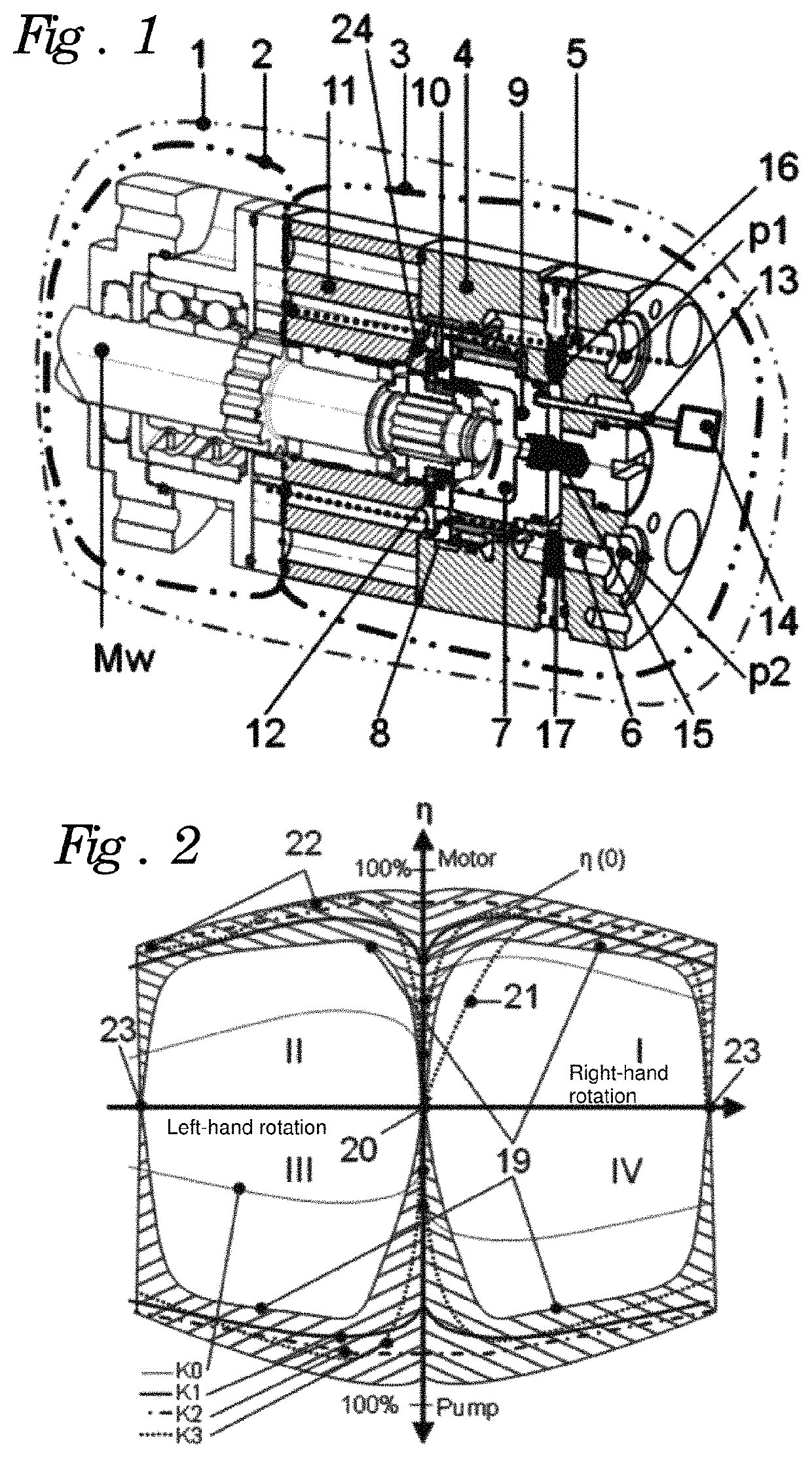
[0026]As is apparent from FIG. 1, the preferred turbomachine 1 is composed of a power section 2 and a controller 3, wherein the power section 2 drives the distributor part 10 via the drive 12. The power section 2 is supplied with rotating inflow and outflow with the two working pressures p1, p2 via the feed part 11. The distributor part 10 is arranged axially with respect to the feed part 11. The piston 9 is arranged axially on the distributor part 10 and is supplied axially with the two driving pressures p1, p2 via the connecting part 4. The piston 9, distributor part 10 and feed part 11 are arranged on the connection part 4. The two connections 5, 6 are in the connecting part 4.

[0027]The control device 13 acts on the piston 9 in the axial direction and is driven here by the drive of the control device 14. The two check valves 16, 17 are arranged between the inner leakage region 7 and the connections 5, 6.

[0028]A further pressure region 8, which is connected to the inner pressure r...


PUM


Abstract

A turbomachine that can be operated as a motor and as a pump, having an axially fixedly mounted shaft, including a power section with rotating inlet and outlet and an associated controller. Because the axial forces (Fgx) have been made independent of the sense of rotation the turbomachine is significantly more reliable, and because the sealing forces have been adjusted it has significantly greater reliability (η) in both running directions. It can be operated with fluids and gases. The turbomachine can be extended by adding a control device and a drive for the control device so as to provide a freewheel function, a braking function and / or blocking function, and so as to shift, modify and optimize the characteristic curves across the entire control range. In both the clockwise and anticlockwise directions the turbomachine has in principle the same properties, although these can be modified and optimized by the control device.

Description

CROSS-REFERENCE TO RELATED APPLICATION[0001]This application is the U.S. national phase of PCT Application No. PCT / DE2014 / 100352 filed on Oct. 8, 2014, which claims priority to DE Patent Application No. 10 2013 111 098.3 filed on Oct. 8, 2013, the disclosures of which are incorporated in their entirety by reference herein.TECHNICAL BACKGROUND[0002]The present invention relates to a turbomachine which can be operated both as a hydraulic motor and as a pump, with a shaft which is mounted in an axially fixed fashion, comprising a power section and a controller which comprises at least one connecting part on which at least one distributor part with through-openings and at least one feed part, are arranged, wherein the distributor part is driven by means of at least one drive which is arranged on the shaft, and axial forces are distributed to a piston which is arranged axially on the distributor part, wherein the at least one inflow and outflow provided on the machine section is configur...

Claims


Application Information

Patent Timeline
Patent Type & Authority Patents(United States)
IPC IPC(8): F04B19/22F04B49/08F04B49/02F04B53/10F04C2/10F04C14/06F04C14/24F01C1/10F01C20/06F01C20/24F03C2/08F04C14/04
CPCF04C14/06F03C2/08F04B49/08F04C2/10F04C2/102F04C14/04F04B49/02
Inventor BAUM, REGINALDRÖSS, ROBERT
Owner BAUM REGINALD
Why Eureka
Try Eureka