Paddle wheel flow meter

a flow meter and paddle wheel technology, applied in the field of paddle wheel flow meter, can solve the problems of signal processing circuit not being able to determine abnormal conditions of disengagement or wear of paddle wheel, probably not being able to generate fluid flow data, etc., and achieve the effect of convenient manufacturing and assembly

Active Publication Date: 2020-09-08
UNITED BENEFIT
View PDF21 Cites 1 Cited by
  • Summary
  • Abstract
  • Description
  • Claims
  • Application Information

AI Technical Summary

Benefits of technology

[0014]In the paddle wheel flow meter according to the present application, the paddle wheel includes two of the disc wheels located at the two sides of the paddles, and at least one of the disc wheel has the magnet disposed therein, so that the paddle wheel is easy to be manufactured and assembled; when the fluid in the fluid pipeline drives the paddle wheel rotat...

Problems solved by technology

When the magnetic field change of the paddle wheel module driven by a low flowing rate of the fluid is too small, the sensing module is probably unable to generate the data of the fluid flow, or generates the fluid flow with great error.
Due the magnetic sensor generates the pulse signal, the signal processing circuit cannot determine abnorm...

Method used


Image

  • Paddle wheel flow meter
  • Paddle wheel flow meter
  • Paddle wheel flow meter

Examples


Embodiment Construction

[0023]The technical features and other advantages of the present application will become more readily apparent to those ordinarily skilled in the art, by referring the following detailed description of embodiments of the present application in conjunction with the accompanying drawing. In order to further clarify the technical means adopted in the present application and the effects thereof, the figures schematically illustrate the relative relationship between the main elements, but is not based on the actual size; therefore, thickness, size, shape, arrangement and configuration of the main elements in the figure are only for reference, not intended to limit the scope of the present application.

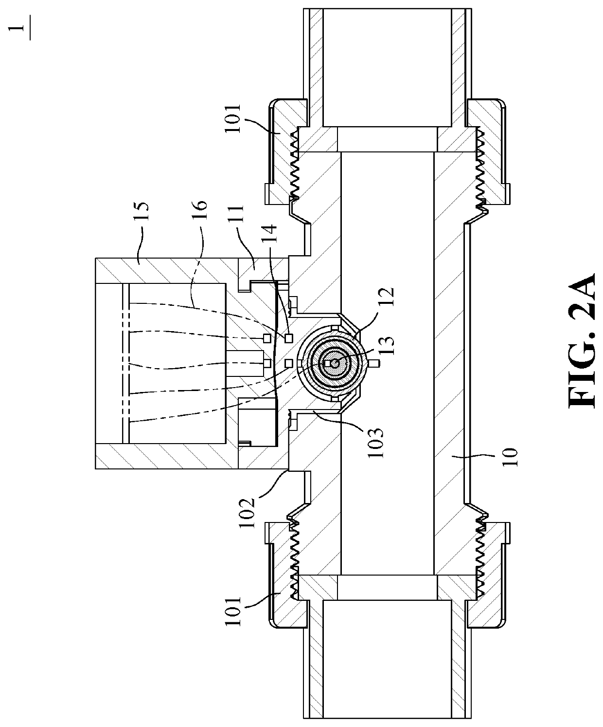
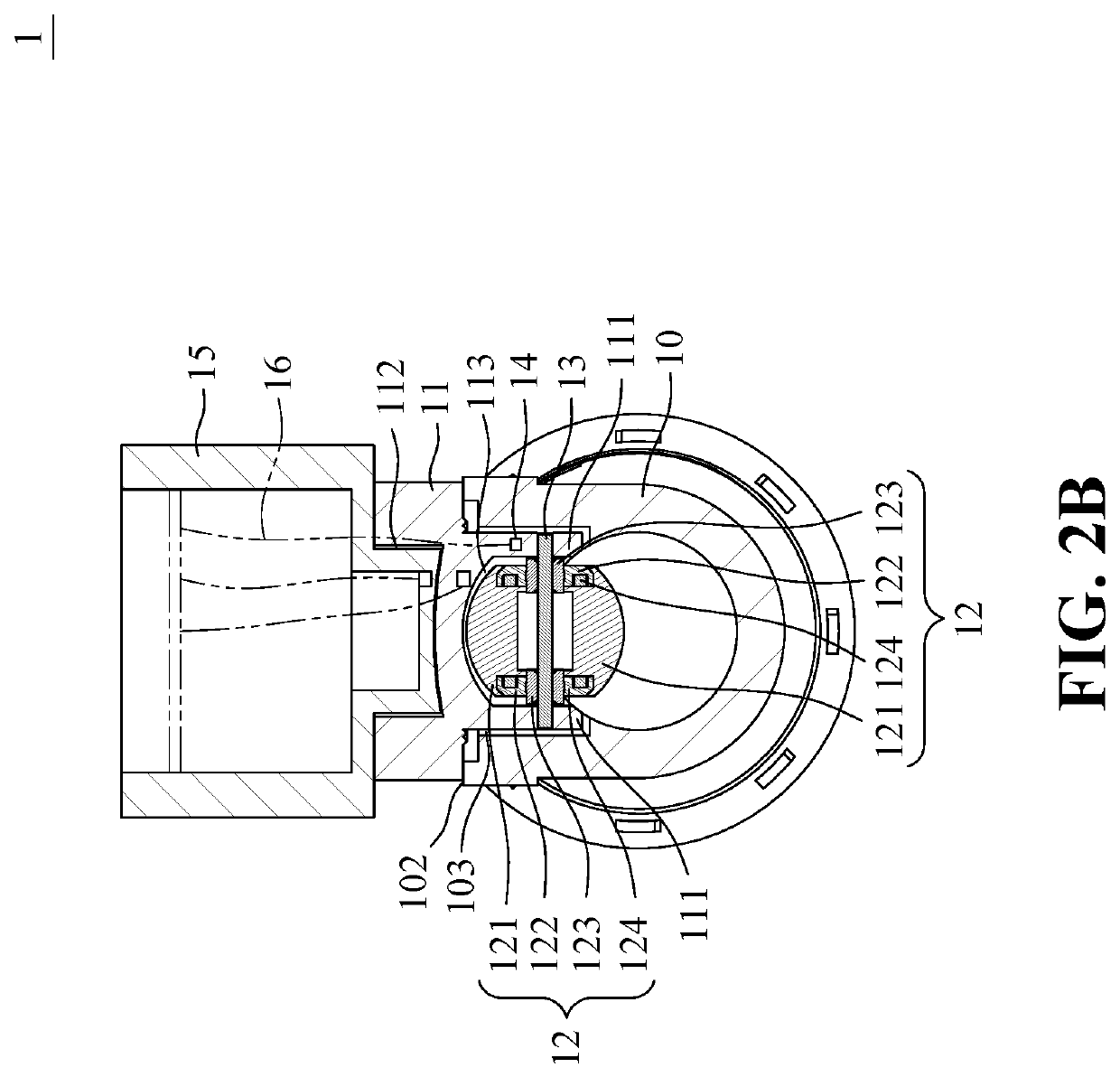
[0024]FIG. 2A is an axially cross-sectional view schematically illustrating the paddle wheel flow meter according to an embodiment of the present application, and FIG. 2B is a radially cross-sectional view schematically illustrating the paddle wheel flow meter shown in FIG. 2A. As shown in F...


PUM


Abstract

A paddle wheel flow meter includes a base, a paddle wheel, an axis and a magnetic sensor. The base is capable of being embedded in a fluid pipeline, and has two lugs. The paddle wheel is disposed between the two lugs, and includes paddles, two disc wheels, two bearings and at least a magnet, wherein the disc wheels are located at two opposite sides of the paddles, the bearings are respectively disposed in the disc wheels, the magnet is disposed in at least one of the disc wheels. The axis has two ends respectively fixed to the lugs through the bearings. The magnetic sensor is disposed in the base. When a fluid in the fluid pipeline drives the paddle wheel rotating, the magnetic sensor generates an electrical signal by sensing a magnetic field change of the magnet.

Description

BACKGROUND OF THE INVENTION1. Field of the Invention[0001]The present application relates to a flow meter, especially to a paddle wheel flow meter.2. The Prior Arts[0002]A paddle wheel flow meter which contacts with a fluid is mainly applied to measure a fluid flow containing less insoluble matter. The paddle wheel flow meter includes a case, a paddle wheel module and a sensing module, wherein the case has a part embedded in a pipeline, the paddle wheel module is disposed in the part of the case embedded in the pipeline, and the sensing module is disposed in the part of the case not embedded in the pipeline. The paddle wheel module includes two wheels, paddles and magnets, wherein the paddles connect to the wheels, and the magnets are disposed in the paddles. The sensing module includes a magnetic sensor and a signal processing circuit. When a fluid in the pipeline drives the paddle wheel module rotating, the magnets disposed in the paddles generates a magnetic field change, the mag...

Claims


Application Information

Patent Timeline
IPC IPC(8): G01F1/06G01F1/075
CPCG01F1/075G01F1/115
Inventor CHANG, YUAN HSE
Owner UNITED BENEFIT
Why Eureka
Try Eureka