Probe device, precision detection method, precision detection system, and positioning system

a detection method and probe technology, applied in the field of medical instruments, can solve the problems of affecting the control precision of the whole surgical robot, affecting the path planning accuracy or precision, etc., and achieve the effect of improving the precision of the guide elemen

Active Publication Date: 2020-09-15
BEIJING TINAVI MEDICAL TECH
View PDF7 Cites 5 Cited by
  • Summary
  • Abstract
  • Description
  • Claims
  • Application Information

AI Technical Summary

Benefits of technology

[0005]The objective of the invention is to improve the precision of a guide element by providing a probe device, a precision detection method, a precision detection system, and a positioning system.

Problems solved by technology

Deformation and wear of the guide element caused in the transportation, storage, sterilization or using process will affect the path planning accuracy or precision.
In addition, due to the fact that the deformation and wear of the guide element are unperceivable, the guide element cannot accurately move to a preset position of a wound of patients during the surgery, which in turn affects the control precision of the whole surgical robot.

Method used


Image

  • Probe device, precision detection method, precision detection system, and positioning system
  • Probe device, precision detection method, precision detection system, and positioning system
  • Probe device, precision detection method, precision detection system, and positioning system

Examples


first embodiment

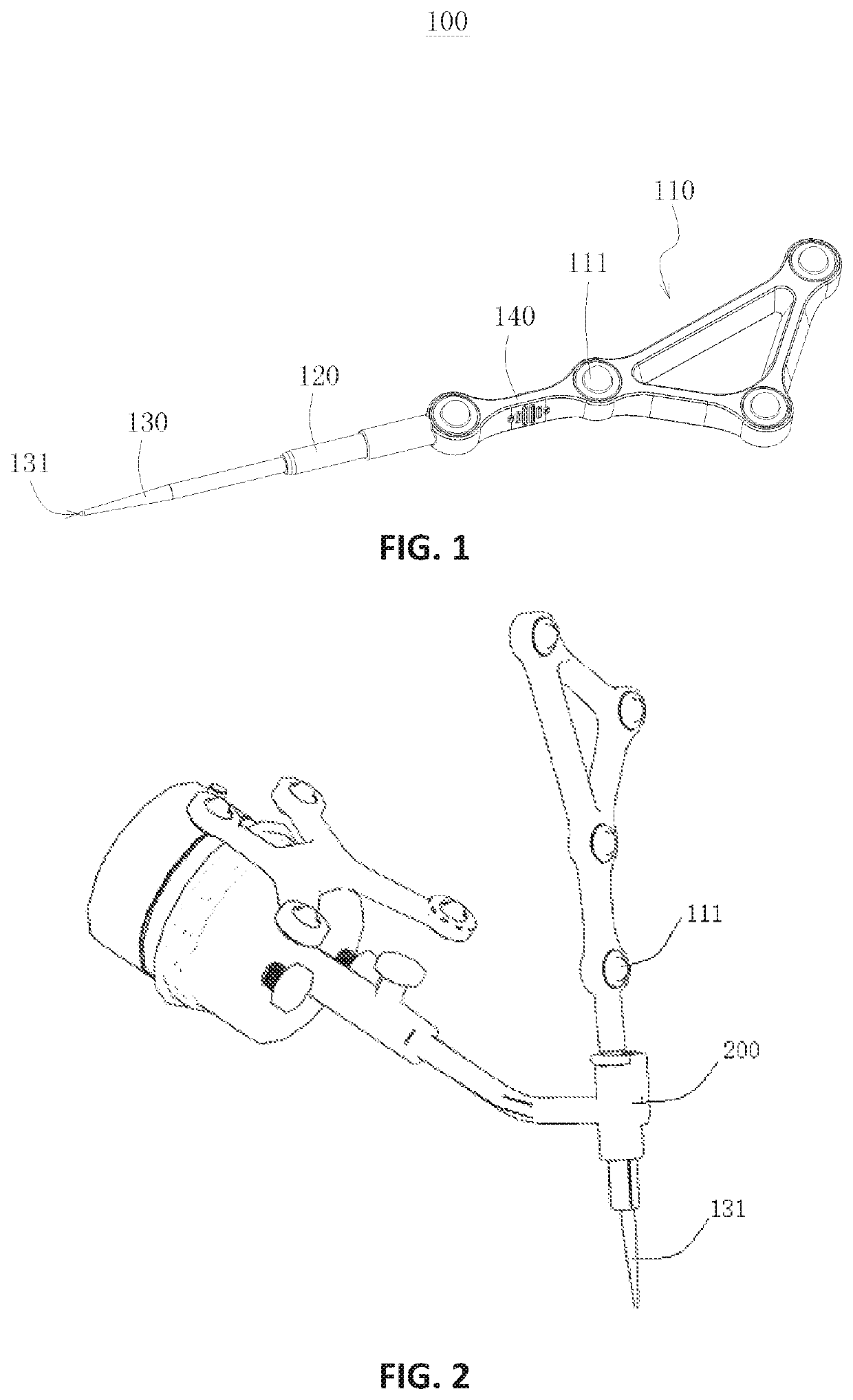
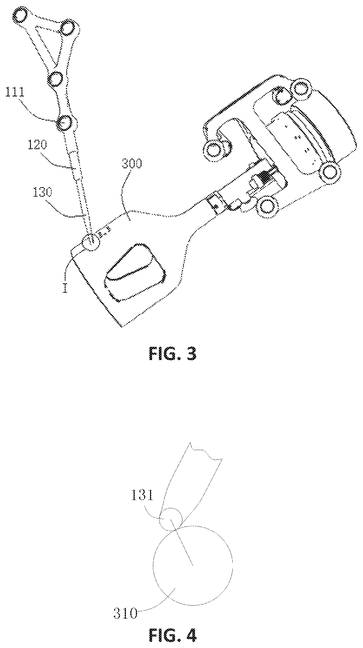
[0034]Please refer to FIG. 1 and FIG. 2, wherein FIG. 1 is a structural diagram of the probe device 100 in the invention, and FIG. 2 is a cooperative structural diagram of the probe device 100 and a guide element 200. The probe device 100 is used for a surgical robot positioning system which generally includes a guide element 200, a position finder, a calibrator 300, and the like. The probe device 100 includes a positioning part 110 and a guide detection part 120, wherein the positioning part 110 is provided with a support having three or more non-collinear positioning elements 111 installed thereon, and the guide detection part 120 is connected with the support, has a first preset positional relation with the positioning elements 111, and has a cylindrical outer contour matched with the guide element 200 of the positioning system.

[0035]Wherein, the number of the positioning elements 111 on the support is not limited and can be three, four, or more. For instance, as shown in FIG. 1,...

fourth embodiment

[0129]the invention provides a positioning system. The positioning system includes a surgical robot, a host computer, a position finder, a guide element 200, a calibrator 300, and a probe device 100 in any of the embodiments mentioned above.

[0130]During orthopedic surgery, the guide element 200 and the calibrator 300 are used for auxiliary guidance and positioning of the surgical robot, the host computer is used for controlling the surgical robot to drive the guide element 200 and the calibrator 300 to move, the position finder is used for acquiring the set positions of the guide element 200 and the calibrator 300 and is also used for recognizing three or more positioning elements 111 and determining the spatial position of a support according to the three or more positioning elements 111, and then the spatial position of the guide detection part 120 is figured out.

[0131]The position finder can be configured in various ways. For instance, the position finder is an infrared receiver ...


PUM


Abstract

The invention provides a probe device, a precision detection method, a precision detection system, and a positioning system. The probe device includes a positioning part and a guide detection part, wherein the positioning part is provided with a support having three or more non-collinear positioning element installed thereon, and the guide detection part is connected with the support, has a first preset positional relation with the positioning elements, and has a cylindrical outer contour matched with a guide element of the positioning system. The precision of the guide element can be accurately detected, so that the control precision of a surgical robot is effectively improved, and the system safety is improved.

Description

CROSS-REFERENCE TO RELATED APPLICATIONS[0001]This application claims priority under 35 U.S.C. § 119(b) to Chinese Patent Application No. 201910349611.X, filed Apr. 28, 2019, which is incorporated herein by reference in its entirety.BACKGROUND OF THE INVENTION1. Technical Field[0002]The invention relates to the technical field of medical instruments, in particular to a probe device, a precision detection method, a precision detection system, and a positioning system.2. Description of Related Art[0003]A surgical robot is generally used for guidance during orthopedic surgery, and the precision of a guide element has a significant influence on the path planning precision. Deformation and wear of the guide element caused in the transportation, storage, sterilization or using process will affect the path planning accuracy or precision. In addition, due to the fact that the deformation and wear of the guide element are unperceivable, the guide element cannot accurately move to a preset pos...

Claims


Application Information

Patent Timeline
Patent Type & Authority Patents(United States)
IPC IPC(8): A61B34/30B25J9/16
CPCA61B34/30B25J9/1664B25J9/1692B25J9/1653A61B34/20A61B90/11A61B2034/2055A61B2034/2068A61B2017/00725
Inventor LI, YINYANCHEN, BOWEI, YUBIAO
Owner BEIJING TINAVI MEDICAL TECH
Why Eureka
Try Eureka