
Reformer for producing synthesis gas having improved burner waste gas flow

a technology of synthesis gas and reformer, which is applied in the direction of hydrogen/synthetic gas production, inorganic chemistry, non-metallic elements, etc., can solve the problems of non-uniform heating of the reformer tube, non-uniform pressure loss from the beginning, and non-uniform turbulen

Active Publication Date: 2020-09-15
LAIR LIQUIDE SA POUR LETUDE & LEXPLOITATION DES PROCEDES GEORGES CLAUDE
View PDF29 Cites 0 Cited by
  • Summary
  • Abstract
  • Description
  • Claims
  • Application Information

AI Technical Summary

Benefits of technology

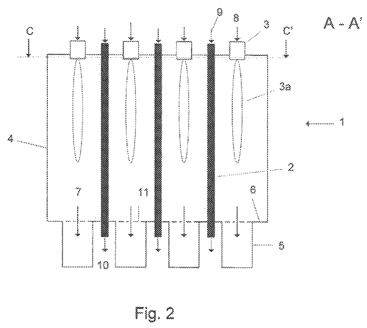
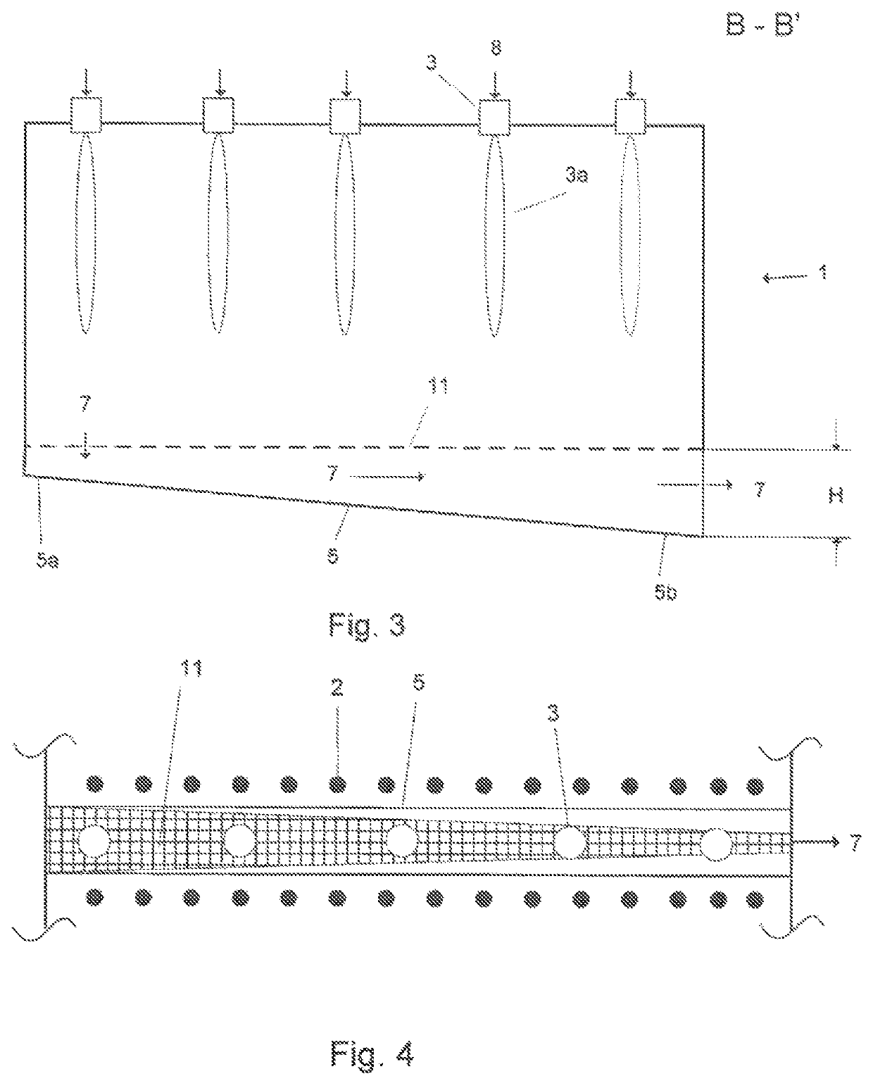
[0021]By keeping the flow velocity constant along the length of the channel in accordance with the invention, the ratio between the dynamic and the static fraction of the pressure, according to the law of conservation of energy according to Bernoulli, likewise remains constant. On the other hand, would the flow velocity increase from the beginning of a channel towards the end of a channel, the static pressure fraction would decrease due to this increase of the dynamic pressure fraction and hence the static pressure difference between the interior spaces of the reformer housing and the channel would rise. This in turn would tend to lead to a stronger extraction of burner waste gas in this region of the channels, which would have to be countered with a reduction of the passage openings between housing and channel.
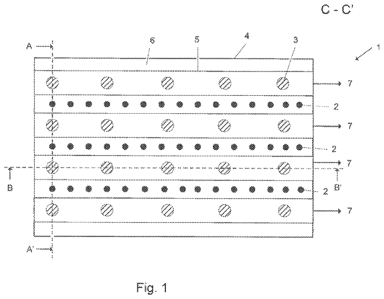
[0029]It furthermore is preferred when the openings in the channel ceilings each are continuous along the entire channel length and have a wedge profile tapering in flow direction. The pressure loss thereby increases along the length of the waste gas channels upon passage of the burner waste gases from the combustion chamber into the channels, so that the burner waste gases can be sucked off more easily from the rear part of the waste gas channels facing away from the suction device.
[0030]The two aforementioned preferred aspects advantageously can be combined, as in this way the change of the channel cross-section and the change of the size of the openings in the channel ceilings between reformer housing and channel are made continuously and without any jumps, which is beneficial for the uniformization of the waste gas flow of the burner waste gas out of the reformer housing. Unilateral mechanical loads of the waste gas channels or the combustion chamber as well as the non-uniform heating of the reformer tubes caused by turbulences thus are reduced.
[0032]A further preferred aspect of the invention is characterized in that the ceilings of the channels each consist of a plurality of plates extending across the entire width of the channel, wherein openings are formed in the channel ceilings in that the plates are placed at distances to each other. In this way, the width of the channel opening is maintained along the entire channel length. The construction and the design of the channels thereby are simplified. The size of the passage openings can be varied in a simple way by exchanging and / or shifting the plates.

Problems solved by technology

The flow resistance which the waste gas stream is subject to within each of the channels leads to a pressure loss from the beginning of a channel to the end of a channel.
This results in non-uniform turbulences in the burner waste gas, which are distributed along the channel length or in the bottom region of the reformer housing, and hence to a non-uniform heating of the reformer tubes.

Method used


Image

  • Reformer for producing synthesis gas having improved burner waste gas flow
  • Reformer for producing synthesis gas having improved burner waste gas flow
  • Reformer for producing synthesis gas having improved burner waste gas flow

Examples


Embodiment Construction

[0028]A preferred aspect of the invention is characterized in that the channels have a wedge-shaped longitudinal profile flared in flow direction from their beginning towards their end. This aspect takes account of the waste gas quantity increasing cumulatively along the length of the waste gas channels.

[0029]It furthermore is preferred when the openings in the channel ceilings each are continuous along the entire channel length and have a wedge profile tapering in flow direction. The pressure loss thereby increases along the length of the waste gas channels upon passage of the burner waste gases from the combustion chamber into the channels, so that the burner waste gases can be sucked off more easily from the rear part of the waste gas channels facing away from the suction device.

[0030]The two aforementioned preferred aspects advantageously can be combined, as in this way the change of the channel cross-section and the change of the size of the openings in the channel ceilings bet...


PUM

PropertyMeasurementUnit
flow velocityaaaaaaaaaa
lengthaaaaaaaaaa
sizeaaaaaaaaaa

Abstract

A steam reformer, with a combustion chamber, catalyst tubes arranged in several rows, with burners for heating the catalyst tubes, with feed conduits each for supplying the catalyst tubes with educt gas and the burners with air and fuel gas, with collecting conduits for discharging the product gas, with channels for discharging the burner waste gases from the combustion chamber, wherein the ceilings of the channels each are formed by the bottom or the ceiling of the combustion chamber, and wherein the channels for discharging the burner waste gases are designed such that the flow velocity of the burner waste gases is constant along the entire length of the channels, as seen vertically to the catalyst tubes.

Description

CROSS REFERENCE TO RELATED APPLICATIONS[0001]This application is a § 371 of International PCT Application PCT / EP2016 / 025104, filed Sep. 28, 2016, which claims the benefit of EP1500044.2, filed Oct. 5, 2015, both of which are herein incorporated by reference in their entireties.FIELD OF THE INVENTION[0002]This invention relates to a steam reformer, comprising:[0003]a combustion chamber with a bottom, a ceiling and side walls terminating the combustion chamber,[0004]catalyst tubes arranged in several rows, which penetrate the bottom and / or the ceiling of the combustion chamber,[0005]burners arranged in the ceiling, the bottom or one or more side walls of the combustion chamber for heating the catalyst tubes,[0006]feed conduits extending below the bottom or above the ceiling of the combustion chamber each for supplying the catalyst tubes with educt gas and the burners with air and fuel gas,[0007]collecting conduits extending below the bottom or above the ceiling of the combustion chamb...

Claims


Application Information

Patent Timeline
Patent Type & Authority Patents(United States)
IPC IPC(8): B01J8/06C01B3/38
CPCC01B3/384B01J8/062C01B2203/0233C01B2203/0816C01B3/38C01B2203/1235
Inventor COSCIA, ANTONIO
Owner LAIR LIQUIDE SA POUR LETUDE & LEXPLOITATION DES PROCEDES GEORGES CLAUDE
Learn More