Portable inflation device

a portable, inflation device technology, applied in the direction of machines/engines, liquid fuel engines, positive displacement liquid engines, etc., can solve the problems of inconvenient storage, lack of portability, and large volume of conventional inflation devices for inflating inflatable apparatuses, so as to reduce the overall volume of inflation devices, enhance inflation rates, and effectively seal inflatable apparatuses

Active Publication Date: 2020-09-15
UNIVERSAL TRIM SUPPLY CO LTD
View PDF8 Cites 0 Cited by
  • Summary
  • Abstract
  • Description
  • Claims
  • Application Information

AI Technical Summary

Benefits of technology

[0003]Therefore, it is an objective of the present application to provide an inflation device which is small in volume, collapsible, portable, and easy to operate.
[0014]In contrast to the prior art, the present application utilizes configuration among the pump body, the upper casing, the middle casing and the lower casing to construct the inflation device with a compact structure for reducing overall volume of the inflation device. The resilient parts adopted in the inflation device can automatically recover from compression, which enhances an inflation rate and is effort-saving. The resilient ventilation plug further operates as a check valve to prevent the inflated air chamber from leakage. In addition, the base, the deflation pin and the spring adopted in the inflation device can ensure a sealing effect when the inflation device inflates the inflatable apparatus and effectively seal the inflated inflatable apparatus. Besides, the present application further provides the inflated inflatable apparatus with easy exhaustion operation. Therefore, the inflation device of the present application is convenient to collapse, portable, effective, and suitable for Inflatable apparatuses such as inflatable clothes, inflatable shoes, and inflatable bags.

Problems solved by technology

However, conventional inflation devices for inflating the inflatable apparatuses are large in volume and inconvenient in storage and lack portability.

Method used


Image

  • Portable inflation device
  • Portable inflation device
  • Portable inflation device

Examples


Embodiment Construction

[0025]In the following detailed description of the preferred embodiments, reference is made to the accompanying drawings which form a part hereof, and in which is shown by way of illustration specific embodiments in which the invention may be practiced. In this regard, directional terminology, such as “top,”“bottom,”“front,”“back,” etc., is used with reference to the orientation of the Figure(s) being described. The components of the present invention can be positioned in a number of different orientations. As such, the directional terminology is used for purposes of illustration and is in no way limiting. Accordingly, the drawings and descriptions will be regarded as illustrative in nature and not as restrictive.

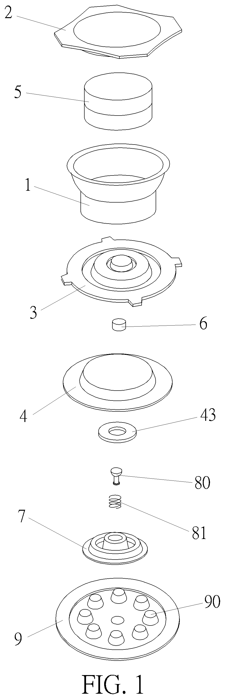
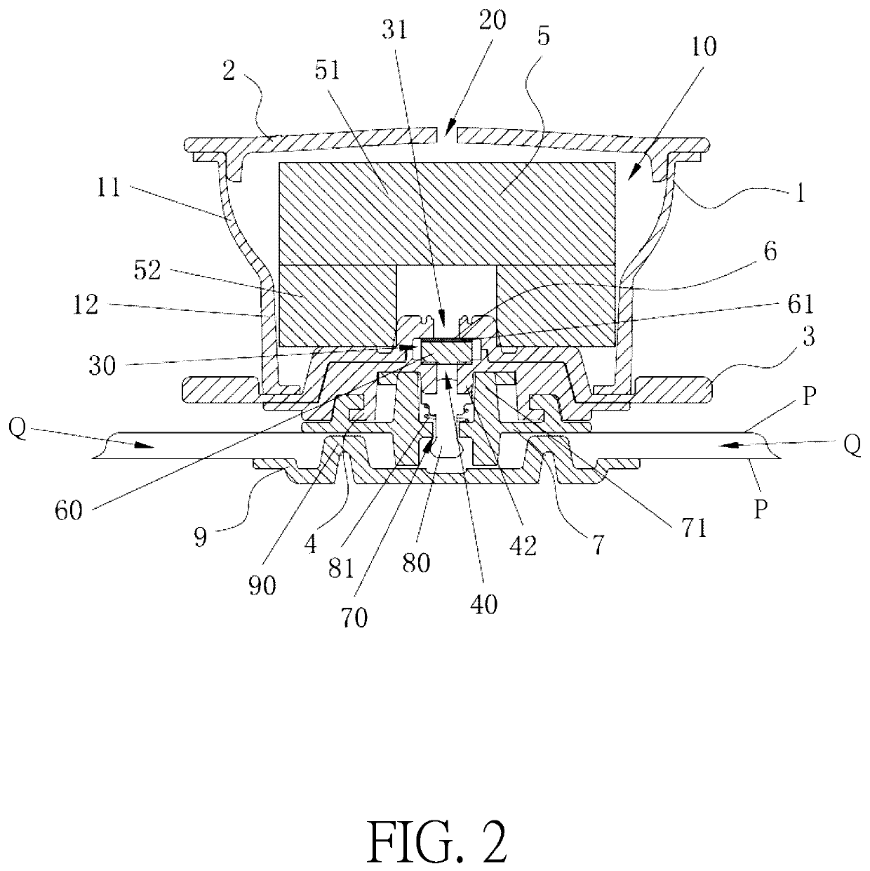
[0026]Please refer to FIG. 1 and FIG. 2. FIG. 1 is an exploded diagram of a portable inflation device according to an embodiment of the present application. FIG. 2 is a sectional diagram of the portable inflation device according to the embodiment of the present application...


PUM


Abstract

A portable inflation device of the present application includes an inflation pump body, an upper casing, a middle casing, a lower casing, a resilient component, and a resilient ventilation plug. The upper casing and the middle casing respectively seal two ends of the inflation pump body, and an air chamber is defined thereamong. An accommodating chamber is defined between the middle casing and the lower casing disposed outside the air chamber. An intake hole, a first ventilation hole and an exhaustion hole are respectively formed on the upper casing, the middle casing and the lower casing. The resilient ventilation plug disposed inside the accommodating chamber includes a perforated foam positioned between the first ventilation hole and the exhaustion hole and an sealing layer covering a surface of the perforated foam facing towards the first ventilation hole. The inflation device is small in volume, collapsible, portable, and easy to operate.

Description

BACKGROUND OF THE INVENTION1. Field of the Invention[0001]The invention relates to an inflation device, and more particularly, to a portable inflation device.2. Description of the Prior Art[0002]Inflatable apparatuses, such as Inflatable clothes, inflatable shoes and inflatable bags, are cushion apparatuses which can be buoyant on water, water-proof, soft and portable. Conventionally, inflatable apparatuses are applied in outdoor activities such as mountain climbing, camping and diving. However, conventional inflation devices for inflating the inflatable apparatuses are large in volume and inconvenient in storage and lack portability. Therefore, it is important to develop an inflation device with portability.SUMMARY OF THE INVENTION[0003]Therefore, it is an objective of the present application to provide an inflation device which is small in volume, collapsible, portable, and easy to operate.[0004]To achieve the aforementioned objective, the present application discloses a portable ...

Claims


Application Information

Patent Timeline
Patent Type & Authority Patents(United States)
IPC IPC(8): F16K13/00F04B33/00F04B39/12A41D27/00A43B3/24F04B53/10
CPCF04B33/00F16K13/00F04B39/121F04B53/10F04B53/1072A41D27/00A43B3/248F04B53/108F04B39/10F04B43/0054
Inventor YANG, SHIH-SHENG
Owner UNIVERSAL TRIM SUPPLY CO LTD
Why Eureka
Try Eureka