
Remotely operated manual welding method and welding robot implementing such a method

a remote-operated, welding robot technology, applied in the direction of manipulators, process and machine control, instruments, etc., can solve the problems of operator exposure to welding fumes, difficulty in automating the degree of expertise, and inconvenient positions of operators, so as to improve the quality of manual assemblies

Active Publication Date: 2020-09-22
COMMISSARIAT A LENERGIE ATOMIQUE ET AUX ENERGIES ALTERNATIVES
View PDF11 Cites 1 Cited by
  • Summary
  • Abstract
  • Description
  • Claims
  • Application Information

AI Technical Summary

Benefits of technology

[0005]One object of the invention is to improve the quality of manual assemblies carried out by the application of heat.SUMMARY OF THE INVENTION
[0017]Thus, the operator's ability to intervene in the welding parameters when necessary is maintained and reinforced by the fact that some parameters are controlled automatically by default. The operator is then able to concentrate fully on the critical parameters and their variation with regard to the behavior of the assembly at the point of application of heat. Remote operation greatly improves the operator's working conditions, notably in respect of his exposure to fumes or UV radiation, and the convenience of the workstation. Finally, the haptic interface maintains the indispensable contribution of the operator's manual skills. The combination of these improvements in the conditions for the execution of the assembly has a positive effect on the quality of the assembly.
[0027]The guidance of the virtual arm and its perception by the operator is then provided by the bilateral coupling which transfers the effect of the guidance forces toward the haptic interface and transfers the effect of the movements of the haptic interface toward the virtual arm. The movement of the articulated arm is provided by the unilateral positional coupling from the virtual articulated arm toward the articulated arm. The use of three-dimensional modeling makes it possible to reduce the resources required for the calculation of the interferences and the determination of the forces to be fed back by the processing and control unit toward the haptic interface. The application of guidance constraints to the virtual articulated arm only makes it possible to reduce the volume of commands to be sent toward the guidance actuators of the articulated arm, which then no longer need to exert resistant forces, but simply guidance forces.
[0029]According to a particular embodiment, the guidance actuators are controlled so as to constrain the point of application of heat to follow the reference path. This allows precise application of the point of application of heat, particularly for butt welds, and thus enables the area affected thermally by the application of heat to be limited, resulting in a higher-quality assembly.
[0030]According to another particular embodiment, step b) of calculating the reference path of the point of application of heat involves the use of at least one of the following parameters: the geometry of a joint plane, the geometry of the elements, and the method of assembly. The operator is then released from operations which do not relate exclusively to controlling the assembly at the point of application of heat, for example operations for controlling the interference of the arm with the elements to be assembled. For the same purpose, the definition of the guidance envelope may take into account at least one of the following requirements: maintaining the orthogonality or a condition of the positioning of the heat application member in relation to the surface of at least one of the elements, keeping the end of the heat application member in a joint plane, and avoiding collisions between the heat application member, the arm and the elements to be assembled.

Problems solved by technology

The large number of parameters to be monitored, and the analysis of the weld pool, require a degree of expertise which it is difficult to automate.
These operators are then exposed to welding fumes, to the UV radiation of the heat source, and sometimes have to assume inconvenient positions, notably during the assembly of cylindrical elements which require what is known as an overhead posture, in which the heat application member is located under the assembly, usually requiring the operator to position the heat application member above him, in a particularly uncomfortable position.
The intervention of an operator affects the repeatability of the assembly operations, and represents a source of uncertainty and therefore of variability in the quality of the completed assembly.
An orbital welding robot virtually requires a robot specific to each tube diameter, and is limited for practical purposes to butt-joined assemblies, ruling out the automation of certain types of assembly such as seam welding.
This lack of versatility makes these robots unsuitable for one-off production or small or medium production runs, which are therefore always handled by manual welding.
Such forms of production therefore suffer from high variability in the quality of the completed assemblies, notably as a result of the particularly trying working conditions for the operators.

Method used


Image

  • Remotely operated manual welding method and welding robot implementing such a method
  • Remotely operated manual welding method and welding robot implementing such a method
  • Remotely operated manual welding method and welding robot implementing such a method

Examples


Embodiment Construction

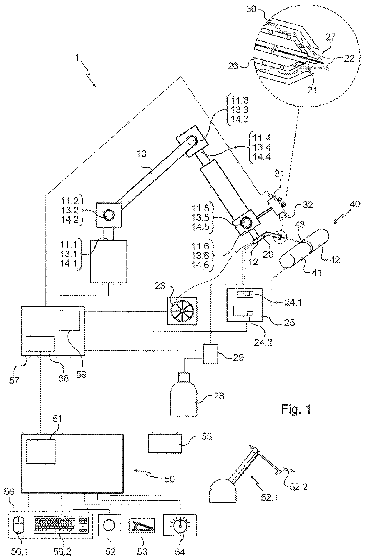
[0049]With reference to FIG. 1, the method is executed by means of a remotely operated robot, designated in a general way by the number 1, comprising a polar arm 10 with six axes, having six joints 11.1 to 11.6 of the rotary type.

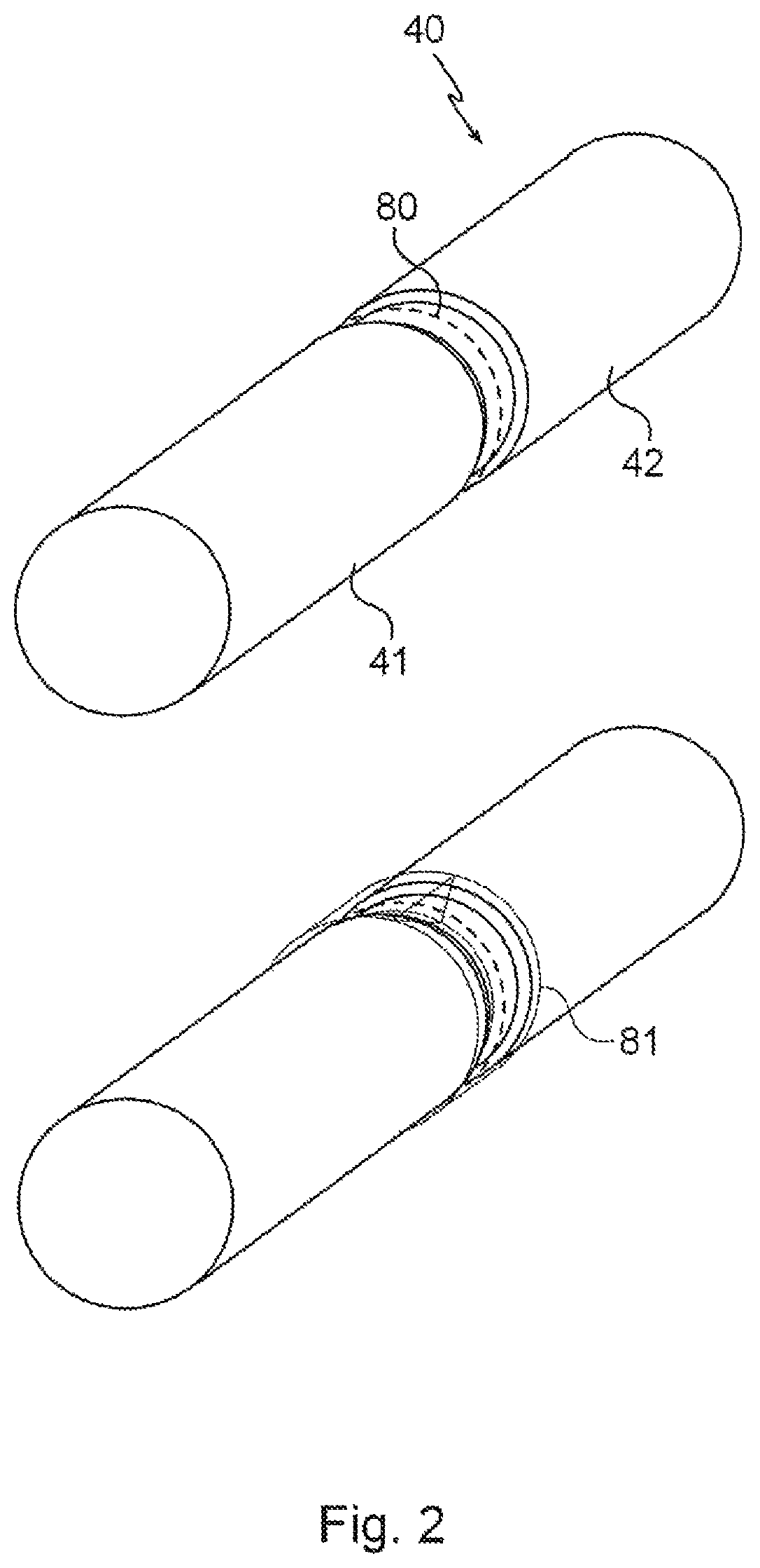
[0050]A MIG welding torch 20 is mounted at the end 12 of the arm 10, and comprises a tubular guide 21 for a metal wire 22 running from a controlled unwinder 23. The guide 21 is connected to the positive terminal 24.1 of an electric welding generator 25. An assembly 40 of two metal tubes 41 and 42 is, for its part, connected to a second, ground terminal 24.2 of the generator 25. Thus the wire 22 acts as an electrode, and enables an electric arc to be struck, delivering heat to a point of application of heat 43 on the assembly 40. The MIG welding torch 20 also comprises a diffuser 26 for supplying shielding gas 27, argon in this case, from a reservoir 28 to which an expansion valve / flow meter assembly 29 is fitted. A tubular nozzle 30 extends around the guide...


PUM


Abstract

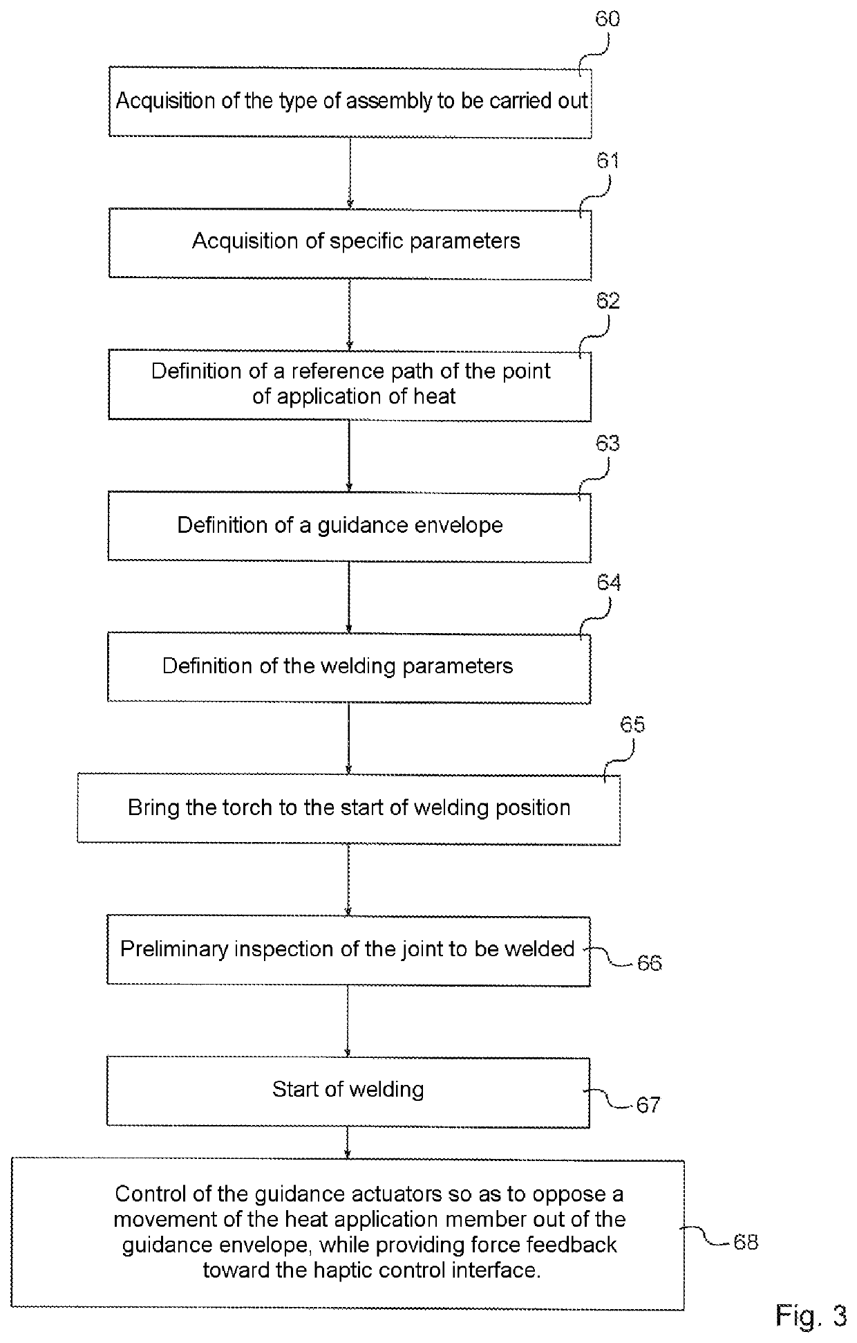
A method to assist with the production of an assembly of two elements implemented by a remotely operated robot. The method includes an arm, hinged to the end of which is mounted a heat-supply member suitable for delivering heat to a heat-supply point; position sensors; guiding actuators; a video capture device; an interface; and a processing unit. The method involves the following steps: acquiring a type of assembly to be produced; calculating a reference path of the heat-supply point; defining a shell for guiding the heat-supply member; and controlling guiding actuators so as to prevent the heat-supply member from moving out of the guiding shell.

Description

CROSS REFERENCE TO RELATED APPLICATIONS[0001]This application is a National Stage of International Application No. PCT / EP2016 / 061330, filed May 19, 2016, claiming priority based on French Patent Application No. 15 54520, filed May 20, 2015, the contents of all of which are incorporated herein by reference in their entirety.TECHNICAL FIELD OF THE INVENTION[0002]The present invention relates to the field of the assembly of elements by the application of heat, such as welding and brazing, and more particularly to assistance in carrying out such assemblies.TECHNICAL BACKGROUND[0003]Welding and brazing are reliable methods for the assembly of metallic or non-metallic elements by the application of heat. The portions of the elements to be assembled are placed facing one another and define a joint plane which is subjected to the application of heat, which may or may not be accompanied by the additional application of joint material. Brazing denotes methods in which the joint is formed by d...

Claims


Application Information

Patent Timeline
Patent Type & Authority Patents(United States)
IPC IPC(8): B25J9/16
CPCB25J9/1689B25J9/1664B25J9/1679G05B2219/40074G05B2219/45135G05B2219/40432G05B2219/36417
Inventor PERROT, YANNDA SILVA SIMOES, MAX
Owner COMMISSARIAT A LENERGIE ATOMIQUE ET AUX ENERGIES ALTERNATIVES
Learn More