
Systems and methods for optimizing rate of penetration in drilling operations

a drilling operation and optimization technology, applied in the field of wellbore construction, can solve the problems of difficult detection of stuck pipes, increased non-productive time for drilling crews, and common problems of stuck pipes while drilling, so as to achieve efficient hole cleaning, optimize performance, and improve drilling efficiency

Active Publication Date: 2020-09-22
SAUDI ARABIAN OIL CO
View PDF15 Cites 0 Cited by
  • Summary
  • Abstract
  • Description
  • Claims
  • Application Information

AI Technical Summary

Benefits of technology

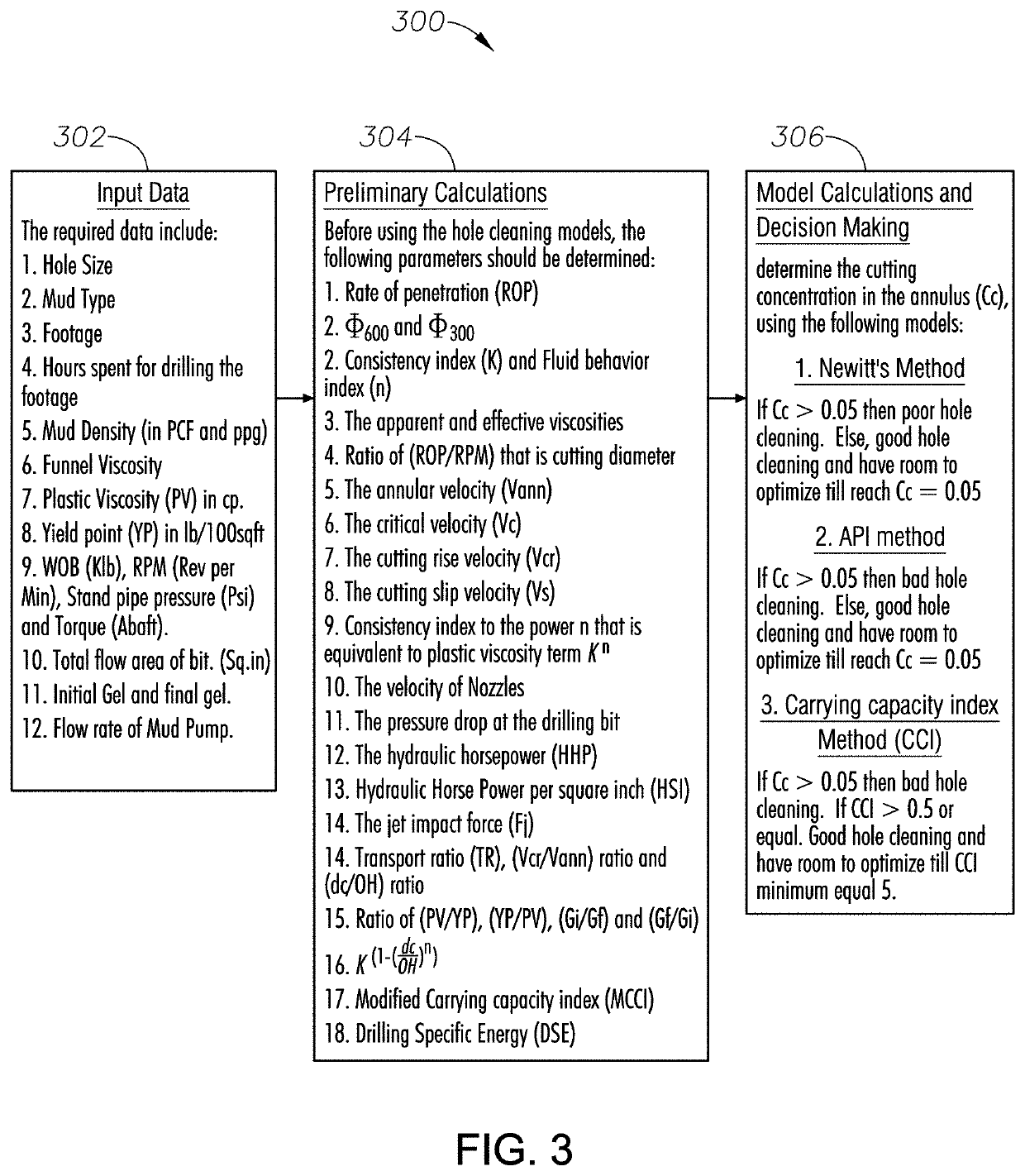
The patent describes systems and methods for efficient hole cleaning in vertical, deviated, and horizontal holes. The methods involve developing a model that integrates hole cleaning and drilling rate using carrying capacity index and cutting concentration in the annulus. The systems and methods also ensure optimum mud rheology values that affect drilling mud from aspects such as equivalent circulating density, cuttings transport, shear thinning, and thixotropic properties. The methods include receiving input parameters of the drilling operation, determining the concentration of cuttings near the drill tool, determining the desired rate of penetration, and altering the current rate of penetration based on the determined concentration. The technical effects of the patent are improved hole cleaning and efficiency of drilling processes using drilling mud.

Problems solved by technology

Stuck pipe while drilling can be a common problem in the oil industry.
In fact, stuck pipe has become a more significant source of non-productive time because extended reach horizontal drilling has gained use in unconventional shale plays.
Unfortunately, stuck pipe is often difficult to detect until after the sticking event has already occurred.
Yet, extended reach horizontal drilling has changed traditional thinking because it reduces the effectiveness of jars by limiting force transfer from the vertical section to the horizontal section of the well.
Consequently, operators have very few ways to detect / prevent stuck pipe so that in some sense nothing can be done to address the issue if it occurs.
Additionally, limits can be placed on ROP based on the ability of surface equipment to simply clean out solids from the mud coming through the flow line.
As will be appreciated, the above methods are highly subjective and may be unreliable.
In short, current techniques to mitigate stuck pipe during drilling are insufficient.

Method used


Image

  • Systems and methods for optimizing rate of penetration in drilling operations
  • Systems and methods for optimizing rate of penetration in drilling operations
  • Systems and methods for optimizing rate of penetration in drilling operations

Examples


Embodiment Construction

[0033]The methods and systems of the present disclosure will now be described more fully hereinafter with reference to the accompanying drawings in which embodiments are shown. The methods and systems of the present disclosure may be in many different forms and should not be construed as limited to the illustrated embodiments set forth herein; rather, these embodiments are provided so that this disclosure will be thorough and complete, and will fully convey its scope to those skilled in the art.

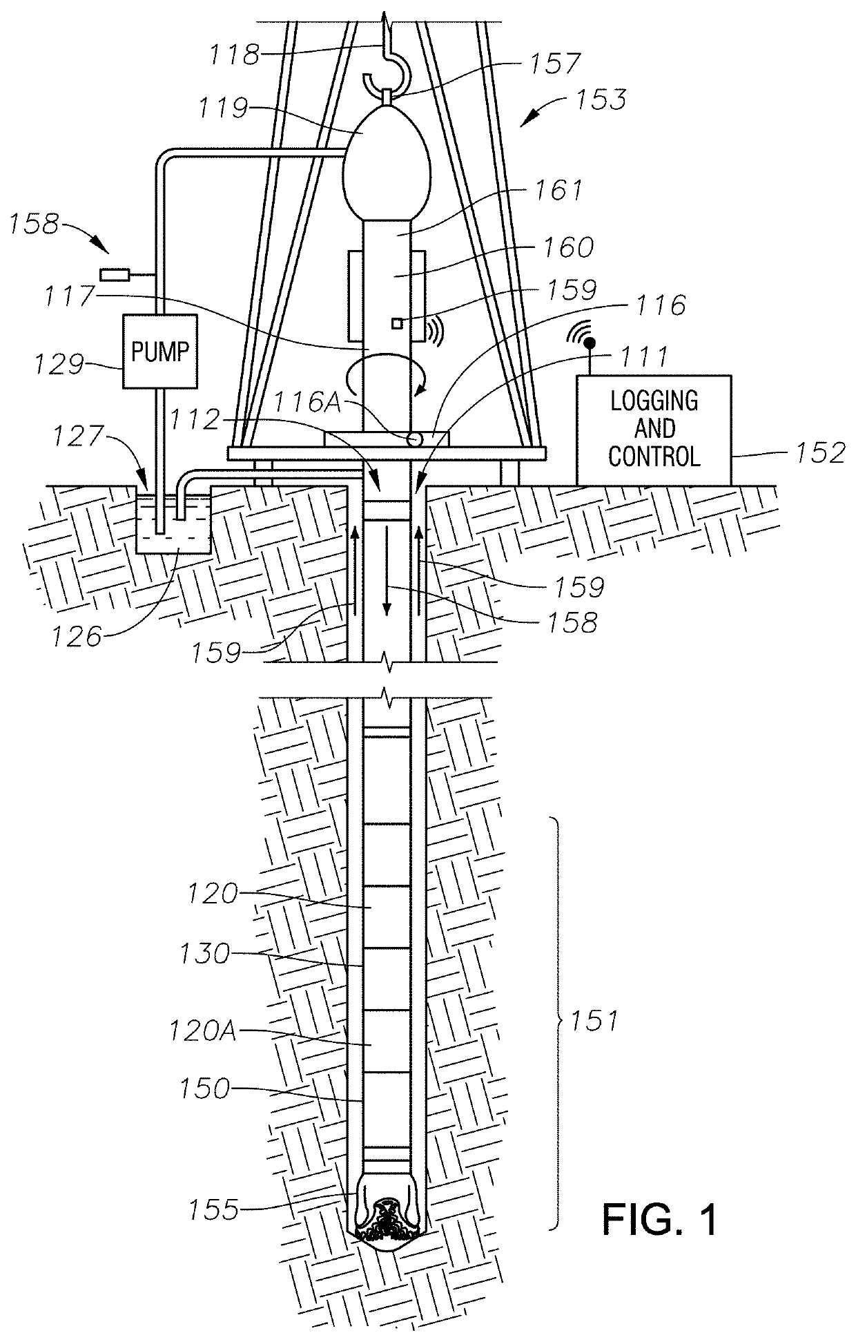
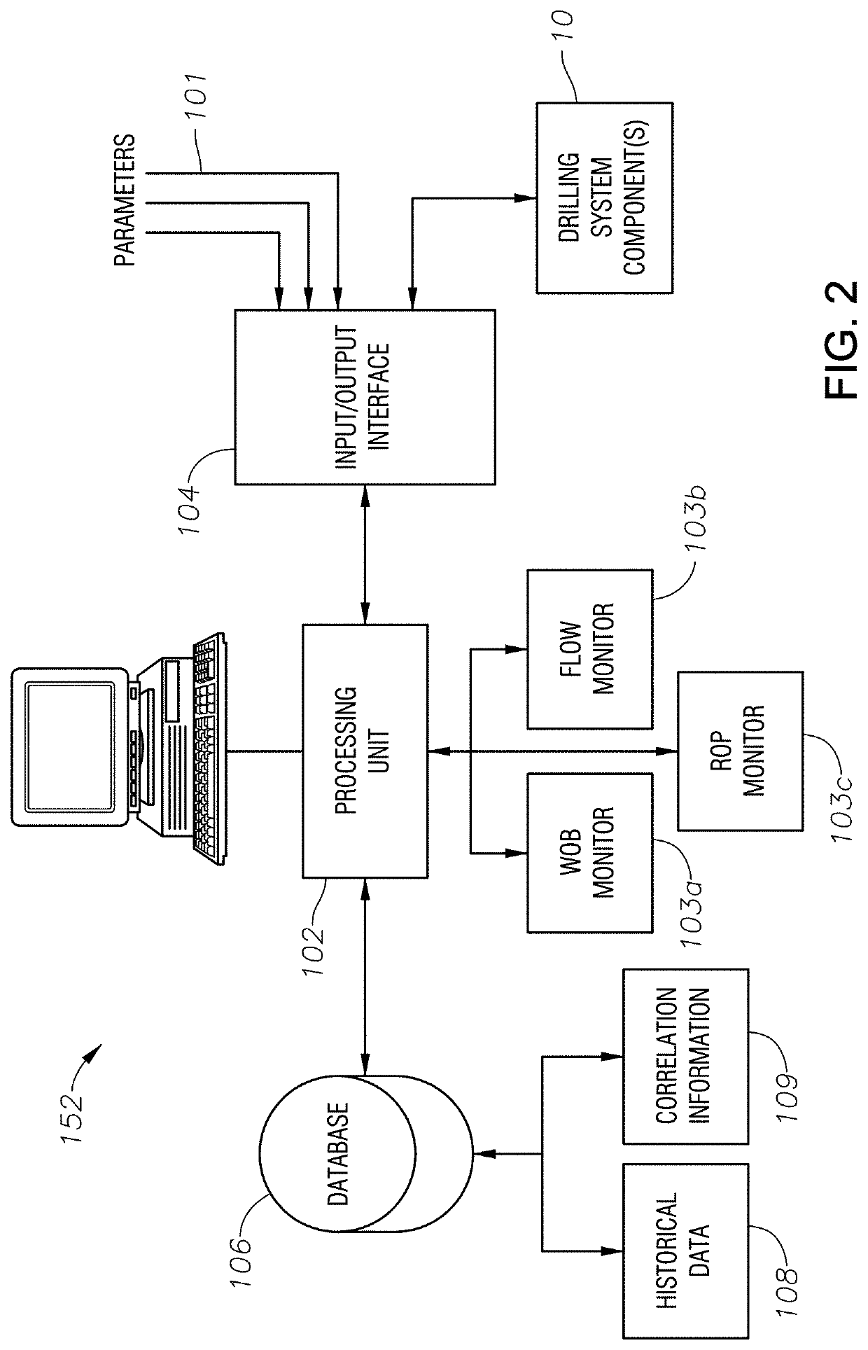
[0034]FIG. 1 shows a simplified view of an example drilling and measurement system that may be used in some embodiments. The drilling and measurement system shown in FIG. 1 may be deployed for drilling either onshore or offshore wellbores. In a drilling and measurement system as shown in FIG. 1, a wellbore 111 may be formed in subsurface formations by rotary drilling in a manner that is well known to those skilled in the art. Although the wellbore 111 in FIG. 1 is shown as being drilled subst...


PUM


Abstract

Systems and methods for predicting an efficient hole cleaning in vertical, deviated, and horizontal holes by developing a hole cleaning model that combines hole cleaning and drilling rate to optimize performance. Specifically by ensuring optimum mud rheology values that have an influence on drilling mud from the aspects of ECD, cuttings transport, shear thinning, and thixotropic, and developing an effective hole cleaning model by utilizing carrying capacity index (CCI) and cutting concentration in annulus (CCA).

Description

BACKGROUND[0001]1. Field[0002]This disclosure relates generally to the field of construction of wellbores through subsurface formations. More particularly the disclosure relates to methods for automatically calculating and displaying to drilling operations personnel values of drilling operating parameters that may optimize drilling of such wellbores and to characterize drilling performance on a specific wellbore with respect to benchmarks for such performance.[0003]2. Description of Related Art[0004]Background[0005]Drilling wellbores through subsurface formations includes suspending a “string” of drill pipe (“drill string”) from a drilling unit or similar lifting apparatus and operating a set of drilling tools and rotating a drill bit disposed at the bottom end of the drill string. The drill bit may be rotated by rotating the entire drill string from the surface and / or by operating a motor disposed in the set of drilling tools. The motor may be, for example, operated by the flow of ...

Claims


Application Information

Patent Timeline
Patent Type & Authority Patents(United States)
IPC IPC(8): E21B44/06E21B47/09E21B3/04E21B45/00E21B21/08E21B49/00
CPCE21B44/06E21B47/09E21B21/08E21B49/005E21B45/00E21B3/04E21B44/00
Inventor AL-RUBAII, MOHAMMED MURIFSEHSAH, OSSAMA R.OMINI, ENO ITAM
Owner SAUDI ARABIAN OIL CO
Learn More