Kiln

a technology of kilns and kilns, which is applied in the field of kilns, can solve the problems of reducing the heating efficiency of kilns, and achieve the effects of improving the exhaust efficiency, enhancing the circulation result of hot air flow inside the cavity, and increasing the exhaust rate of hot air flow

Active Publication Date: 2020-09-29
TEN WING SCIENTFIC CO LTD +1
View PDF12 Cites 1 Cited by
  • Summary
  • Abstract
  • Description
  • Claims
  • Application Information

AI Technical Summary

Benefits of technology

[0007]The advantage of the present invention is that by transferring part of the heat of the heat storage member to the interior of the air guide structure, the exhaust channel could be heated to form rising of steams which generates an upward pulling force to increase an exhaust rate of the hot air flow, whereby the exhaust efficiency could be improved, and the circulation result of the hot air flow inside of the cavity could be enhanced.
is that by transferring part of the heat of the heat storage member to the interior of the air guide structure, the exhaust channel could be heated to form rising of steams which generates an upward pulling force to increase an exhaust rate of the hot air flow, whereby the exhaust efficiency could be improved, and the circulation result of the hot air flow inside of the cavity could be enhanced.

Problems solved by technology

However, the exhaust pipe only exhausts air through chimney effect, and only provides a limited exhaust effect which could not effectively improve a circulation of the hot air flow inside of the stove, thereby reducing a heating efficiency of the kilns.

Method used


Image

  • Kiln
  • Kiln
  • Kiln

Examples


Embodiment Construction

[0025]The following illustrative embodiments and drawings are provided to illustrate the the present invention and its advantages and effects so it can be clearly understood by persons skilled in the art after reading the disclosure of this specification.

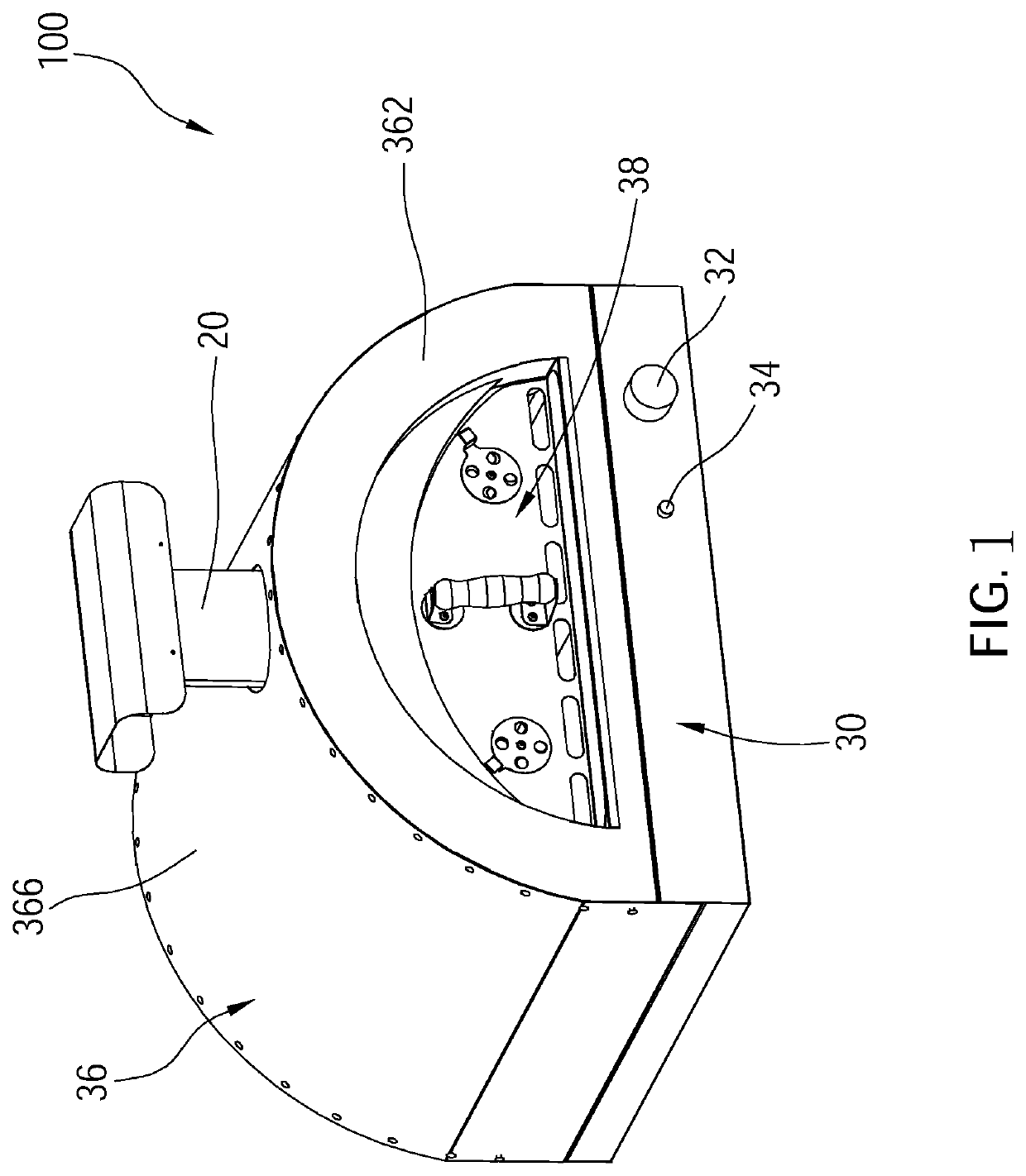
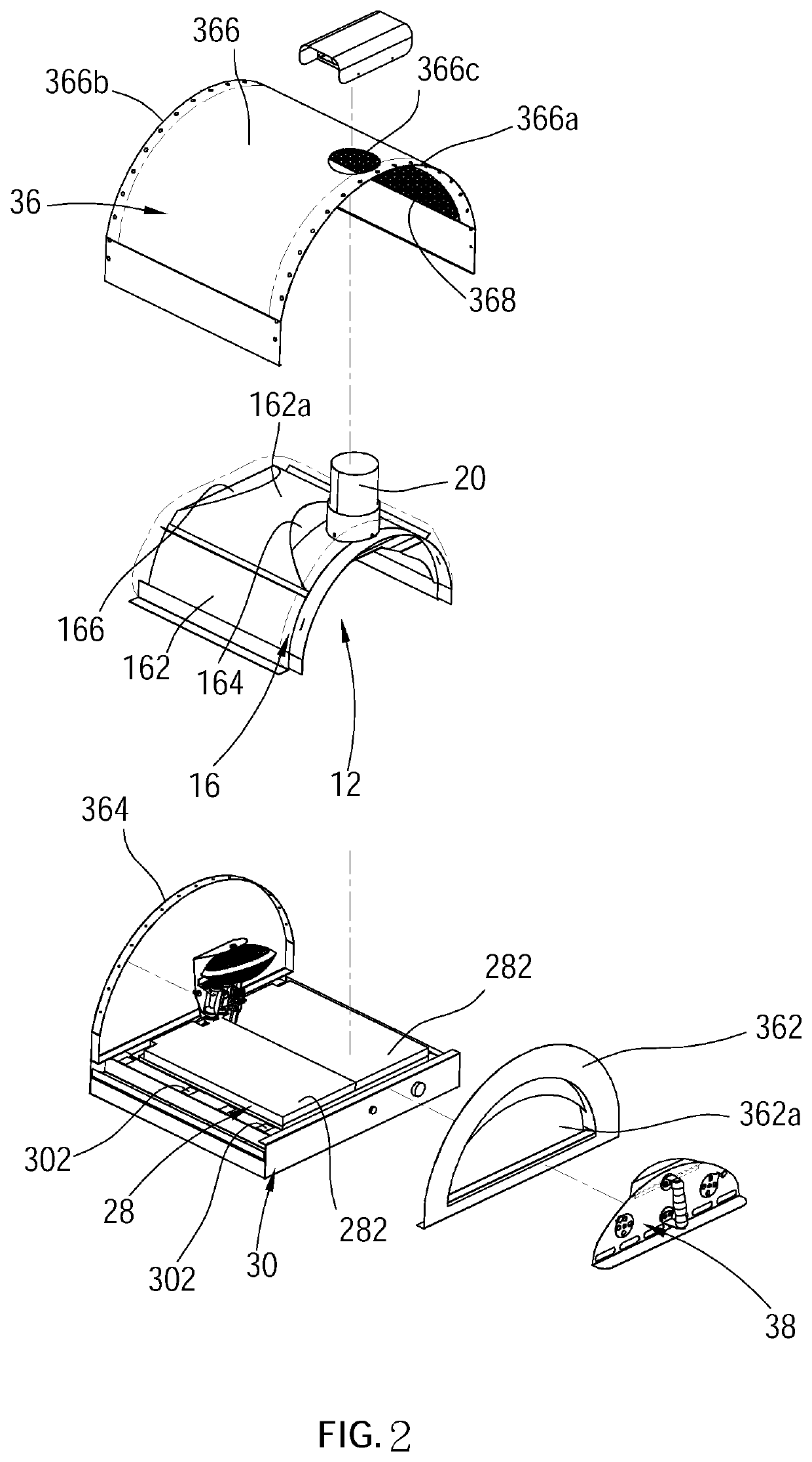
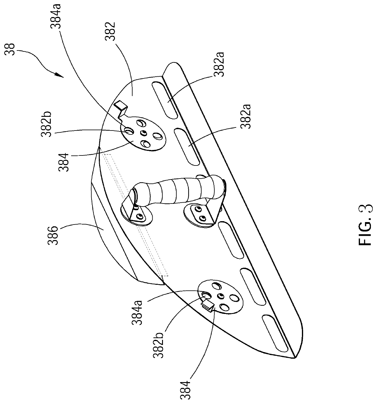
[0026]As illustrated in FIG. 1 to FIG. 10, a kiln 100 of a first embodiment according to the present invention includes a stove 10, a housing 36, a door 38, and a heat source which is a combustion device 40 as an example.

[0027]The stove 10 includes a cavity 12 and an entry 14. The cavity 12 includes a front section 122 and a rear section 124. The front section 122 communicates with the entry 14, and a top wall surface at the front section 122 tilts toward the entry 14 downwardly. The rear section 124 is away from the entry 14. An inner wall surface 124a is located at the rear section 124 and faces the entry 14. A top wall surface at the rear section 124 tilts upwardly in a direction away from the inner wall surface 124a. The cavity ...


PUM


Abstract

A kiln including a stove and a heat source wherein the stove includes a chamber, an air guide structure, an exhaust pipe and a heat storage member. The chamber includes a cavity, an entry, and an air outlet. The air outlet is located between a top of the front section of the cavity and the entry. The air guide structure communicates with the air outlet and includes a guide plate. The exhaust pipe is disposed above the guide plate, and an exhaust channel is formed by the guide plate of the air guide structure and the exhaust pipe. The heat storage member covers an exterior of the cavity which is corresponding to the top of the front section of the cavity, and contacts the air guide structure. The heat source is disposed in the stove and adapted to heat the cavity.

Description

BACKGROUND OF THE INVENTION1. Technical Field[0001]The present invention is related to a heating apparatus, and more particularly to a kiln.2. Description of Related Art[0002]Conventional kilns are adapted for cooking food, such as baking pizza, roasting chicken, stewing vegetables, etc. The stove of conventional kilns is usually built by stacking stone material, and an entry is formed at the front side of the stove to communicate with an inside of the cavity. During the stove is in use, woods are placed into the cavity via the entry and then be ignited to heat the cavity. When the cavity is heated to a temperature suitable for baking food, food ingredients are provided into the cavity via the entry so as to cook the food.[0003]The stove of conventional kilns further includes an exhaust pipe adapted to exhaust waste air out of the stove. However, the exhaust pipe only exhausts air through chimney effect, and only provides a limited exhaust effect which could not effectively improve ...

Claims


Application Information

Patent Timeline
Patent Type & Authority Patents(United States)
IPC IPC(8): F27B17/00F27D7/00F24B1/24A21B1/02A21B1/28F27D1/00
CPCF27B17/0083F24B1/24F27D7/00A21B1/02A21B1/28F27D2001/0073F27M2001/08A47J37/0623A47J37/0664
Inventor TSENG, HSI-MINGLIAO, LI-CHIH
Owner TEN WING SCIENTFIC CO LTD
Why Eureka
Try Eureka