Mixer assembly for mixing an additive with an exhaust gas flow

a technology of mixing assembly and additive, which is applied in the direction of mechanical equipment, engine components, machines/engines, etc., can solve the problems of large structural space required for the exhaust gas line, uneven droplet load of additive, and unsatisfactory nitrogen oxide formation, etc., and achieve high nitrogen oxide reduction rates.

Inactive Publication Date: 2018-08-30
CONTINENTAL AUTOMOTIVE GMBH
View PDF8 Cites 0 Cited by
  • Summary
  • Abstract
  • Description
  • Claims
  • Application Information

AI Technical Summary

Benefits of technology

[0005]The invention is therefore based on the object of providing an

Problems solved by technology

In internal combustion engines, in particular diesel engines or lean-burn engines, undesirably high quantities of nitrogen oxides are formed.
It has however been found that even such depressions, despite the swirling that is generated, generate an uneven droplet load of the

Method used


Image

  • Mixer assembly for mixing an additive with an exhaust gas flow
  • Mixer assembly for mixing an additive with an exhaust gas flow
  • Mixer assembly for mixing an additive with an exhaust gas flow

Examples


Embodiment Construction

[0036]The following description of the preferred embodiment(s) is merely exemplary in nature and is in no way intended to limit the invention, its application, or uses.

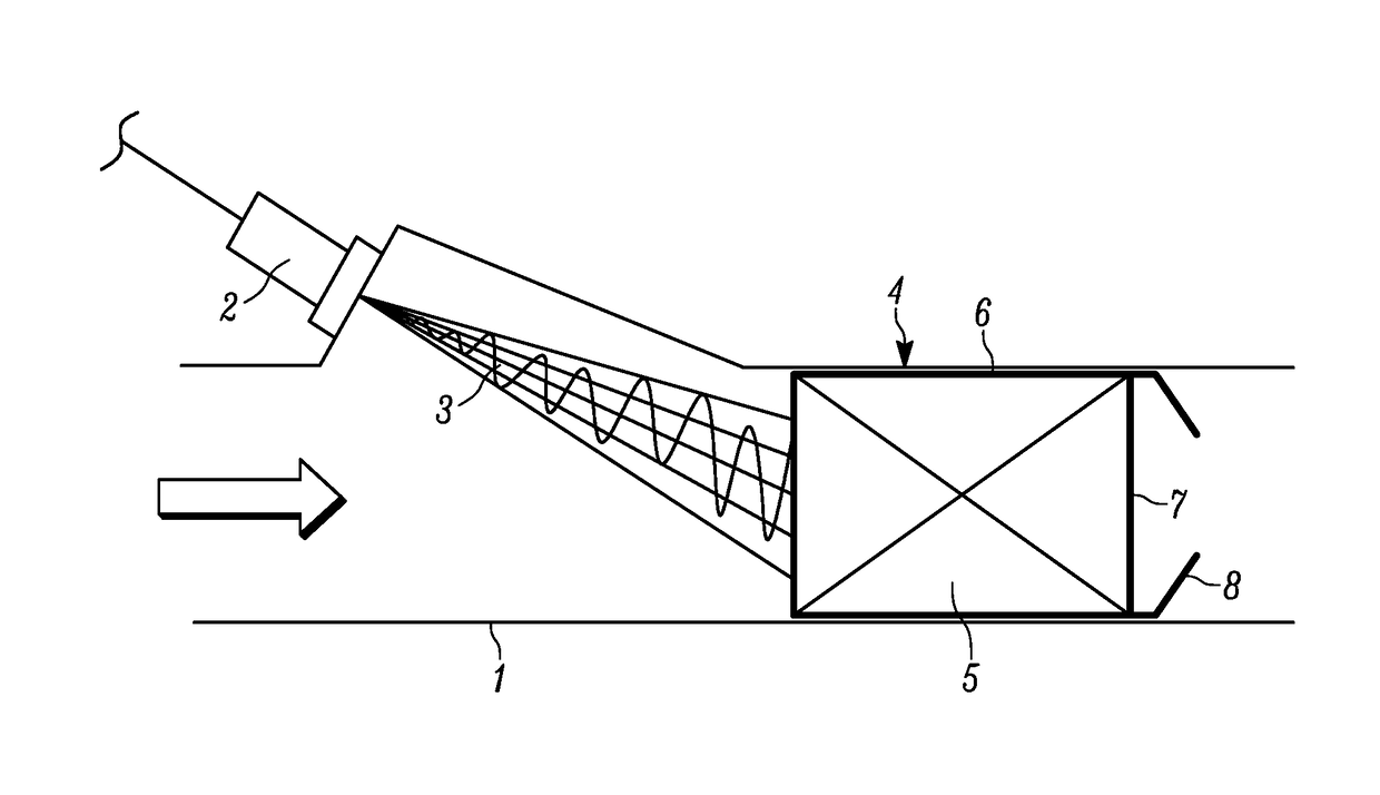
[0037]FIG. 1 shows a mixer arrangement having an exhaust-gas line 1 in a motor vehicle (not illustrated in any more detail). The arrow indicates the main flow direction of the exhaust gas flowing through the exhaust-gas line 1. By means of an injector 2 arranged on the exhaust-gas line 1, urea solution is injected into the exhaust-gas flow at an angle with respect to the main flow direction, such that the jet 3 strikes an exhaust-gas purification element 4 approximately centrally. The exhaust-gas purification element is an SCR catalytic converter 4. The SCR catalytic converter 4 is composed of a schematically illustrated honeycomb body 5, which forms a flow-over surface for the exhaust gas, and a casing 6, which fully encloses the honeycomb body 5. On the downstream-facing side 7 of the casing 6, a guide structure 8 i...


PUM


Abstract

A mixer arrangement for mixing an additive with an exhaust-gas flow, having an exhaust-gas line, an exhaust gas flowing through the exhaust-gas line in a main flow direction, and having at least one exhaust-gas purification element which is arranged in the exhaust-gas line and which has a casing and, arranged within the casing, a flow-over surface for the exhaust gas. Here, the casing of the at least one exhaust-gas purification element has a guide structure.

Description

CROSS-REFERENCE TO RELATED APPLICATIONS[0001]This application claims the benefit of PCT Application PCT / EP2016 / 076308, filed Nov. 1, 2016, which claims priority to German Patent Application 10 2015 221 438.9, filed Nov. 2, 2015, and German Patent Application 10 2015 221 432.2, filed Nov. 1, 2015. The disclosures of the above applications are incorporated herein by reference.FIELD OF THE INVENTION[0002]The invention relates to a mixer arrangement for mixing an additive with an exhaust-gas flow, having an exhaust-gas line, an exhaust gas flowing through the exhaust-gas line in a main flow direction, and having at least one exhaust-gas purification element which is arranged in the exhaust-gas line and which has a casing and, arranged within the casing, a flow-over surface for the exhaust gas.BACKGROUND OF THE INVENTION[0003]In internal combustion engines, in particular diesel engines or lean-burn engines, undesirably high quantities of nitrogen oxides are formed. A suitable approach fo...

Claims


Application Information

Patent Timeline
IPC IPC(8): F01N3/28F01N3/20
CPCF01N3/2892F01N3/2821F01N3/2066F01N2610/02F01N2330/02F01N2330/38F01N3/206
Inventor MUELLER-HAAS, KLAUS
Owner CONTINENTAL AUTOMOTIVE GMBH
Why Eureka
Try Eureka