Display device

a technology of a display device and a display screen, applied in the field of display devices, can solve the problems of urgent need for heat dissipation and formation of empty steps, and achieve the effect of improving image quality and improving luminan

Active Publication Date: 2020-10-13
LG DISPLAY CO LTD
View PDF3 Cites 0 Cited by
  • Summary
  • Abstract
  • Description
  • Claims
  • Application Information

AI Technical Summary

Benefits of technology

[0010]Another object of the present disclosure is to provide a display device configured such that a fixing unit reflects a portion of the light emitted from a light source on the upper surface of a light guide plate, thereby improving luminance at a light-incident part of the light guide plate.
[0013]The fixing unit may include a reflection member for improving luminance at a light-incident part of a light guide plate, thereby improving image quality.

Problems solved by technology

Consequently, there is an urgent necessity for heat dissipation.
However, an empty step is formed in a portion of the space between the liquid crystal panel and the backlight unit.

Method used


Image

  • Display device
  • Display device
  • Display device

Examples


Embodiment Construction

[0020]Hereinafter, exemplary embodiments of an organic light-emitting display device according to the present disclosure will be described in detail with reference to the accompanying drawings so that the present invention will be easily realized by those skilled in the art. In the drawings, the same elements are denoted by the same reference numerals even when they are depicted in different drawings. In the following description of the present invention, a detailed description of known functions and configurations incorporated herein will be omitted when the same may obscure the subject matter of the present invention. Those skilled in the art will appreciate that some features in the drawings may be exaggerated, reduced, or simplified for ease of description thereof, and that drawings and elements thereof are not always shown at the accurate scale.

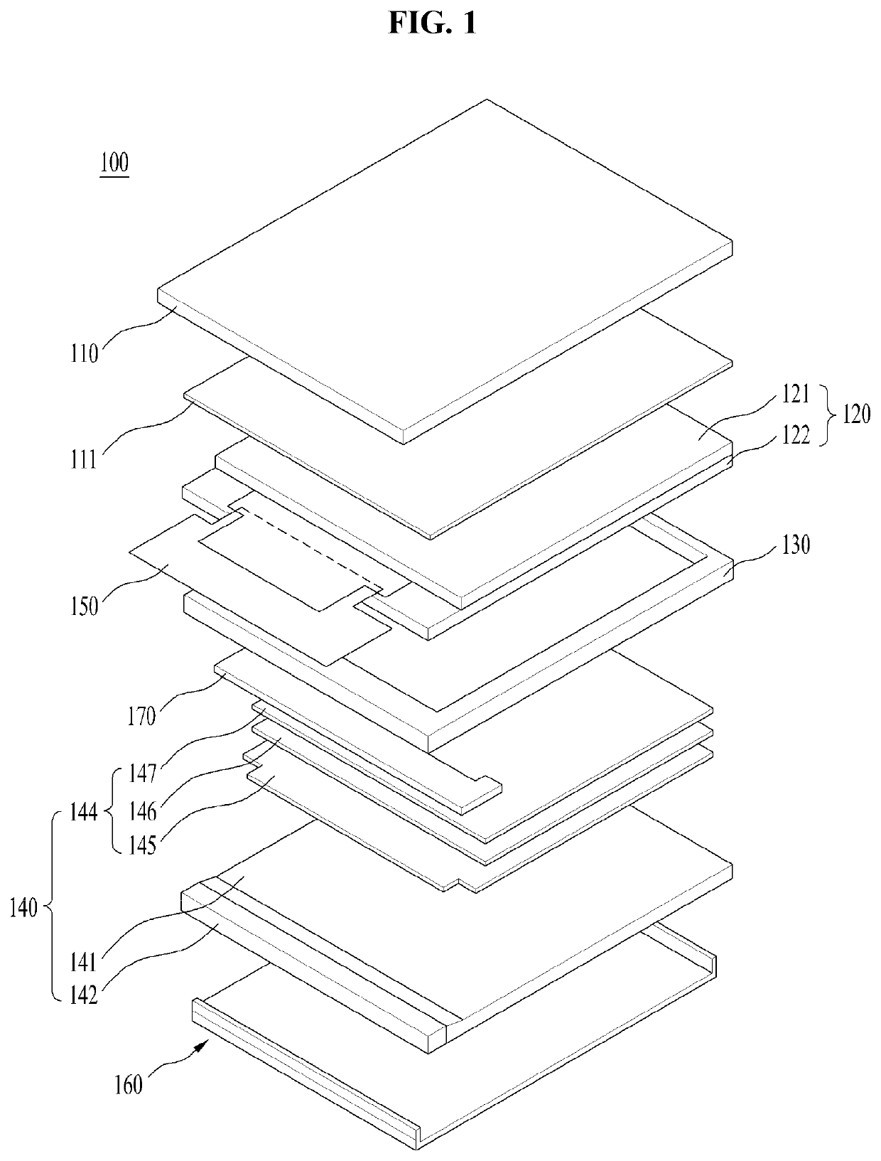
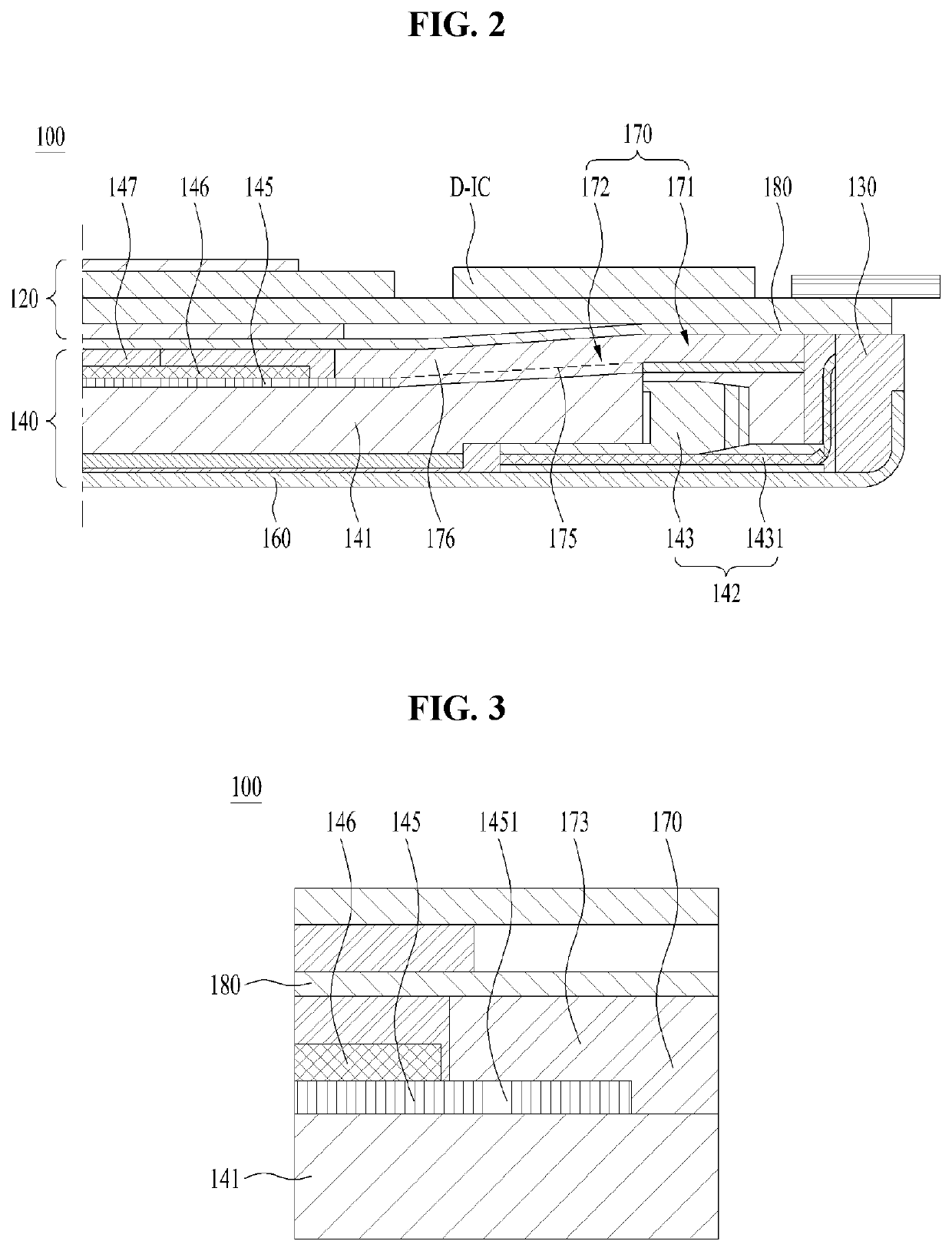
[0021]FIG. 1 is an exploded perspective view showing a display device according to an embodiment of the present disclosure, and FIG. 2 ...


PUM

PropertyMeasurementUnit
flexibleaaaaaaaaaa
weightaaaaaaaaaa
optical anisotropyaaaaaaaaaa

Abstract

Disclosed is a display device configured such that a fixing unit is provided in an empty space between a liquid crystal panel and a light guide plate of a backlight unit in order to support the liquid crystal panel together with a mold and to fix an optical sheet and such that the fixing unit is provided with a reflection member in order to improve luminance at a light-incident part of the light guide plate, whereby image quality is improved.

Description

CROSS-REFERENCE TO RELATED APPLICATIONS[0001]This application claims the benefit of Republic of Korea Patent Application No. 10-2017-0177132, filed on Dec. 21, 2017, which is hereby incorporated by reference in its entirety.BACKGROUNDField of Technology[0002]The present disclosure relates to a display device including a liquid crystal panel and a backlight unit.Discussion of the Related Art[0003]Recently, in the information-oriented society, the importance of display devices as visual information transmission media has been further emphasized. In order to occupy important positions in the future, requirements such as low power consumption, slimness, reduction in weight, and high image quality must be satisfied.[0004]Display devices may be classified into self-emissive display devices, such as a cathode ray tube (CRT) display device, an electro luminescence (EL) display device, a light-emitting diode (LED) display, a vacuum fluorescent display (VFD) device, a field emission display (...

Claims


Application Information

Patent Timeline
Patent Type & Authority Patents(United States)
IPC IPC(8): G02F1/1333F21V8/00G02F1/1335G02F1/13357
CPCG02F1/133308G02B6/0073G02B6/0051G02F2203/02G02B6/0088G02F2001/133314G02F2001/133507G02F2202/28G02F2201/46G02F2001/133317G02F2001/133322G02F1/133615G02F1/133608G02F1/133606G02F1/133605G02B6/0086G02B6/0053G02B6/0055G02F1/133314G02F1/133607G02F1/133317G02F1/13336G02F1/1335G02F1/133322G02F1/133507
Inventor KIM, KYOUNG-JAECHO, WOO-SEOK
Owner LG DISPLAY CO LTD
Why Eureka
Try Eureka