Conveyor chain and transverse member monitoring apparatus

a technology of transverse member and monitoring apparatus, which is applied in the direction of chemistry apparatus and processes, separation processes, sedimentation separation, etc., can solve the problems of skewed or misaligned transverse members, damage to the conveyor or its component chains and transverse members, and the motor, if used,

Active Publication Date: 2020-10-20
BRENTWOOD INDS
View PDF31 Cites 49 Cited by
  • Summary
  • Abstract
  • Description
  • Claims
  • Application Information

AI Technical Summary

Problems solved by technology

The transverse members may become skewed or misaligned by wear of either of the parallel chains, especially if the chains wear unevenly, wear on sprockets driving the chains, slipping, especially uneven slipping, of one or both chains on one or all sprockets, and for other reasons.
If the transverse members are not within the predetermined tolerance, they will be skewed and misaligned, which may cause damage to the conveyor or its component chains and transverse members, belts if used, the motor driving the conveyor, and articles or material being conveyed.
This flight alignment system is difficult to install, is difficult to set up properly, and can freeze in cold climates due to contact with the wet flights causing damage or loss of flight alignment.
However, the system had operation concerns if a flight was removed during maintenance because the flight acted as the target for the position sensor mechanism.
Field setup was difficult due to consistently spacing flights along the length of the chain, while locating cam blocks to mount the flights to the chains the correct distance from the flights required a high level of precision.
The use of cam blocks added additional moving parts, increased the complexity of installation and presented issues in submerged and cold weather applications.
In certain basin configurations, sufficient structure did not exist to support the sensors, therefore expensive and elaborate structural bracketry was required.
Maintenance actions requiring the removal of the flight or changes to the periodicity of the flight within the endless loop of chain cause a simple mechanical system to be limited in its operation within a treatment plant.
Tooth hop is the leading cause of flight misalignment, as both chains do not necessarily hop concurrently due to varying operational load and wear.

Method used


Image

  • Conveyor chain and transverse member monitoring apparatus
  • Conveyor chain and transverse member monitoring apparatus
  • Conveyor chain and transverse member monitoring apparatus

Examples


Embodiment Construction

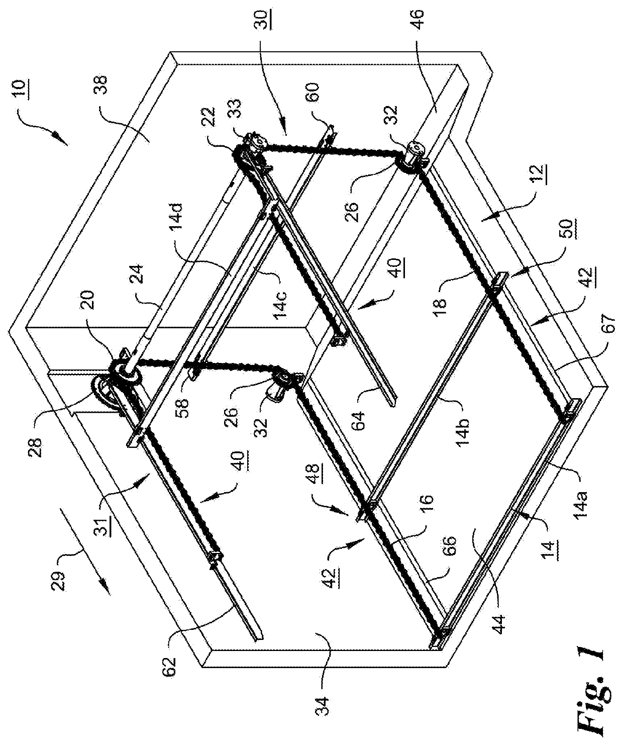
[0051]FIG. 1 is an isometric partial view of one embodiment of a water treatment sediment settlement basin 10 showing a conveyor 12, sometimes called a collector in view of the collection of floating scum and sinking solids in this environment, with a merely exemplary number of flights or transverse members 14, variously identified by numerals 14a, 14b, 14c and 14d in FIG. 1. The flights can be in the form of extruded C-channel shaped members, rectangular members or can have other cross-sections with further reinforcement or stiffness ribs and flanges, or other appropriate shapes, and can be made of fiberglass or other appropriate strong and durable material. The flights 14, are attached as explained below transversely to parallel endless chains 16 and 18, and are spaced from one another, preferably, but not necessarily evenly along the length of the chains. Only portions of the length of the endless chains are shown in FIG. 1, primarily to show one embodiment of the present inventi...


PUM

PropertyMeasurementUnit
lengthaaaaaaaaaa
lengthaaaaaaaaaa
lengthaaaaaaaaaa

Abstract

Apparatus for monitoring alignment of a transverse member conveyor. The member is attached transversely at opposite end portions to two parallel endless chains includes two position sensors affixed and located transversely adjacent to each chain and each other. One or more targets are attached to link(s) of each chain, and at predetermined distances from the member. The position sensors inductively or magnetically sense the relative position of the target(s) on each chain with respect to the respective position sensor adjacent the chain, and send a signal comparing the target and sensor proximity with respect to the target on each chain. This allows determination of whether the opposite end portions of the member attached to the respective chains are aligned transversely within predetermined tolerance limits. Another aspect is monitoring a single position on an endless chain. Another aspect monitors chain catenary.

Description

CROSS-REFERENCE TO RELATED APPLICATIONS[0001]This application claims the priority as a Section 371 U.S. national phase application of International Patent Application No. PCT / US17 / 23830, filed on Mar. 23, 2017 and titled, “Conveyor Chain and Transverse Member Monitoring Apparatus,” the entire contents of which is incorporated herein by reference in its entirety.BACKGROUND OF THE INVENTION[0002]One aspect of the present invention is directed to apparatus, systems and methods for monitoring conveyors driven by endless parallel chains and the alignment of any transverse bars, screens or other transverse members (hereinafter, generally, “members”) that extend and are connected by end portions to the chains. In some embodiments, the conveyor can have a continuous belt, mesh, segments or other hinged surfaces (hereinafter “belt”) connected to the chains, with the transverse members above the belt. In these embodiments, the transverse members could be integral to the chain; either in its e...

Claims


Application Information

Patent Timeline
Patent Type & Authority Patents(United States)
IPC IPC(8): B65G43/02B65G43/04B65G19/24B65G19/10B01D21/22
CPCB65G19/10B65G43/02B65G43/04B65G19/24B01D21/22B65G2203/0283B65G2203/0233B65G2203/043B65G23/44
Inventor KULICK, III, FRANK M.RYE, PETERHABERMEHL, LUKE ELLISRUCH, JASON C.FREDERICKS, CHRISTOPHER STEPHANMITCHELL, ALEX IVANOVICH
Owner BRENTWOOD INDS
Why Eureka
Try Eureka