Tamping unit and method for tamping a track

a technology of tamping unit and track, which is applied in the direction of mechanical vibration separation, solid separation, ways, etc., can solve the problems of unfavorable tamping effect, high counterforce, and difficulty in implementing the latter in a known vibration drive with eccentric shaft, so as to reduce the power consumption of the vibration drive, reduce noise, and improve the effect of rotation speed

Active Publication Date: 2020-10-20
PLASSER & THEURER EXPORT VON BAHNBAUMASCHINEN GESELLSCHAFT MBH
View PDF14 Cites 2 Cited by
  • Summary
  • Abstract
  • Description
  • Claims
  • Application Information

AI Technical Summary

Benefits of technology

[0010]It is further advantageous if the adjustment device comprises at least one hydraulic cylinder with a piston, wherein an adjustment force can be exerted upon the eccentric by means of the piston. Thus it is possible to use a hydraulic system, often already present, to carry out an adjustment of the eccentric relative to the shaft.
[0021]In this, it is advantageous if, in at least one phase of the tamping cycle, an axis distance is set to zero in order to suspend the vibration for a desired duration independently of the speed of rotation of the shaft. This is expedient particularly during a repositioning of the tamping unit between two tamping operations in order to diminish noise and to reduce power consumption of the vibration drive.

Problems solved by technology

In particular, when tamping a ballast bed which has not been renewed and which is often totally encrusted, high counterforces act upon the tamping tine which is set in vibrations by means of the vibration drive.
In the absence of specific measures, an increased ballast bed resistance here leads to an undesired reduction of the vibration amplitude.
The latter is more difficult to implement in a known vibration drive with eccentric shaft, based on the inertia of the masses which are in rotation.

Method used


Image

  • Tamping unit and method for tamping a track
  • Tamping unit and method for tamping a track
  • Tamping unit and method for tamping a track

Examples


Embodiment Construction

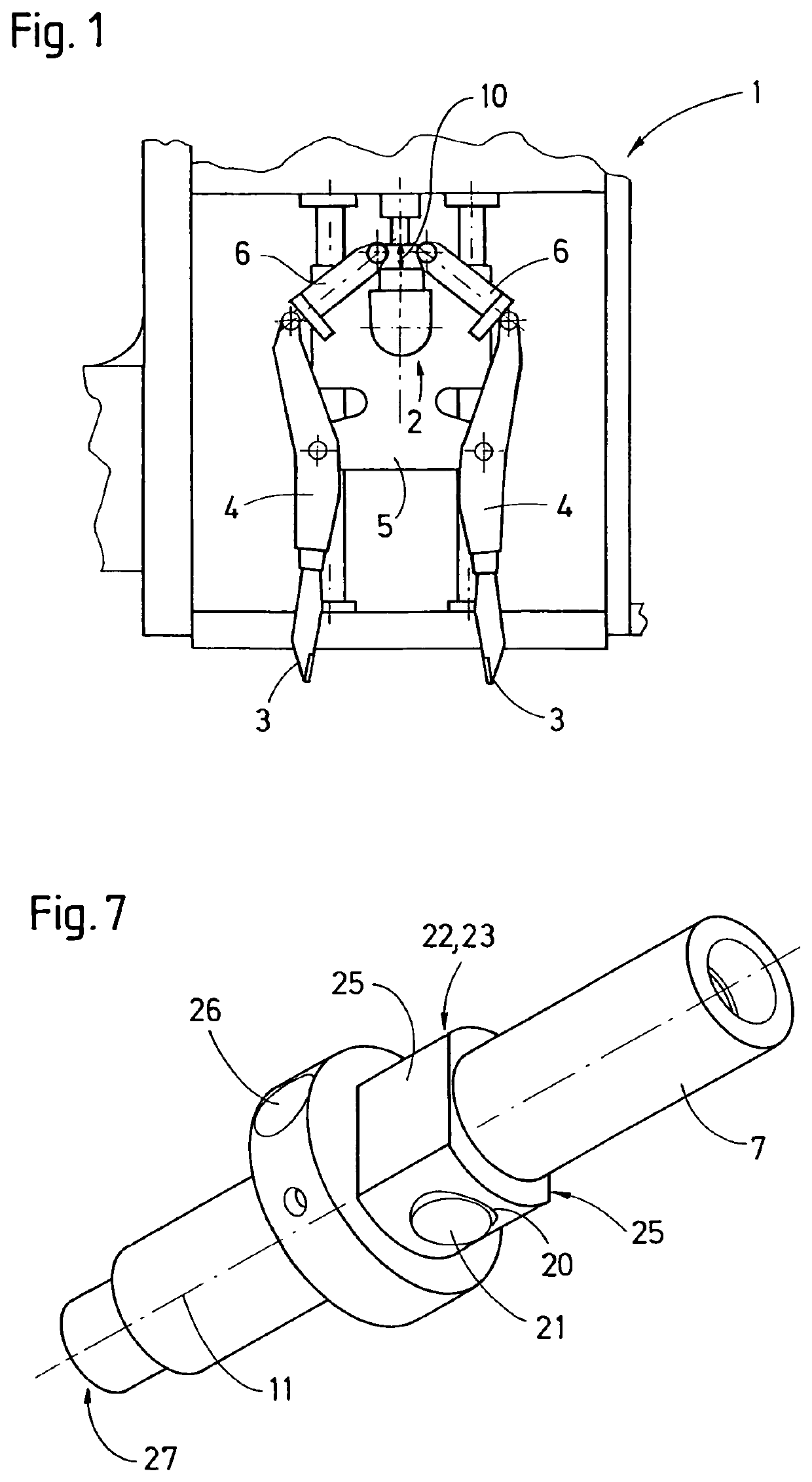
[0031]The tamping unit 1 shown in FIG. 1 comprises an adjustable vibration drive 2 for setting in vibration two oppositely positioned tamping tines 3 or tamping tine groups. In this, each tamping tine 3 is fastened to a tine arm 4. The respective tine arm 4 is pivotally linked to a tamping tine carrier 5, designed to be lowered, and connected to a piston rod of an associated squeezing cylinder 6. Also fastened to the tamping tine carrier 5 is the vibration drive 2 to which each tine arm 4 is connected via the associated squeezing cylinder 6. A generated vibration is thus transmitted via the respective squeezing cylinder 6 to the respective tine arm 4 and the tamping tine 3 fastened thereto.

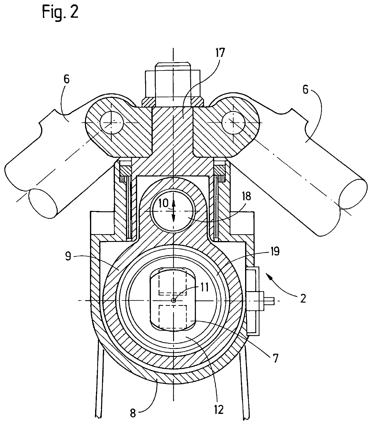
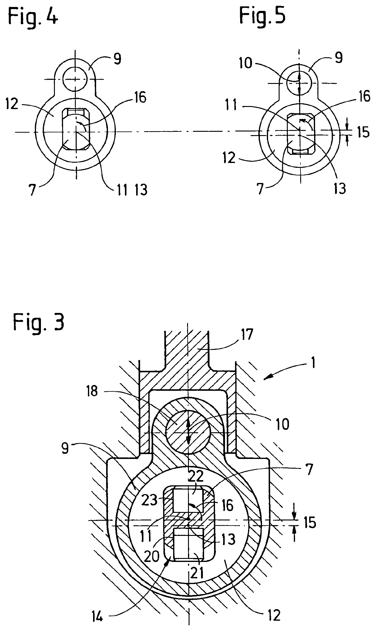
[0032]As visible in FIG. 2, the vibration drive comprises a shaft 7 which is mounted in a housing 8 with sealed passages. At least one additional sealed passage is provided for a transmission element 9 to which the squeezing cylinders 6 of the tamping unit 1 are connected. Advantageously, the shaf...


PUM


Abstract

A tamping unit for tamping a track has tamping tines which are designed for immersion into a ballast bed and which can be set in vibrations by a vibration drive. The vibration drive includes a housing in which a shaft including an eccentric is arranged for rotation about a shaft axis. A transmission element for transmitting a vibratory motion is mounted on the eccentric. The eccentric is connected to the shaft in a rotation-locked and radially displaceable manner, wherein the position of the eccentric relative to the shaft is adjustable in radial direction by an adjustment device. Thus, while retaining the advantages of an eccentric drive, it is possible to adjust vibration parameters during operation.

Description

FIELD OF TECHNOLOGY[0001]The invention relates to a tamping unit for tamping a track, having tamping tines which are designed for immersion into a ballast bed and can be set in vibrations by means of a vibration drive, wherein the vibration drive comprises a housing in which a shaft including an eccentric is arranged for rotation about a shaft axis and wherein a transmission element for transmitting a vibratory motion is mounted on the eccentric. The invention further relates to a method of tamping a track by means of the tamping unit, wherein the generated vibratory motion is transmitted via a squeezing drive to a tine arm.PRIOR ART[0002]Due to the great strain which a tamping unit is subjected to, the vibration drive must fulfil special requirements. During immersion of the tamping tine into a ballast bed of a track, and during the subsequent compaction of the ballast underneath a sleeper, load changes occur constantly which stress the vibration drive. In particular, when tamping ...

Claims


Application Information

Patent Timeline
Patent Type & Authority Patents(United States)
IPC IPC(8): E01B27/17E01B27/16E01B27/20B06B1/16B07B1/44
CPCE01B27/20E01B27/16E01B27/17B06B1/164B06B1/162B07B1/44E01B2203/127E01B2203/12
Inventor SEYRLEHNER, GEORG
Owner PLASSER & THEURER EXPORT VON BAHNBAUMASCHINEN GESELLSCHAFT MBH
Why Eureka
Try Eureka