
Ultrasonic transducer chip assembly, ultrasound probe, ultrasonic imaging system and ultrasound assembly and probe manufacturing methods

a technology of ultrasonic transducer and manufacturing method, which is applied in the direction of mechanical vibration separation, instruments, catheters, etc., can solve the problems of increasing the overall diameter of the ultrasound probe, rather cumbersome manufacturing such a probe, etc., and achieves a cost-effective and high-quality manufacturing process. , the effect of improving stability

Active Publication Date: 2020-10-27
KONINKLJIJKE PHILIPS NV
View PDF31 Cites 0 Cited by
  • Summary
  • Abstract
  • Description
  • Claims
  • Application Information

AI Technical Summary

Benefits of technology

The invention is about creating a small ultrasonic transducer that is easy to make.

Problems solved by technology

However, it is rather cumbersome to manufacture such an ultrasound probe, as each probe has to be manufactured individually.
Moreover, because the backing block encapsulates the PCB, the overall diameter of the ultrasound probe is increased, which is a disadvantage if the ultrasound probe is to be used to image small compartments, e.g. when used in cardiac imaging applications.

Method used


Image

  • Ultrasonic transducer chip assembly, ultrasound probe, ultrasonic imaging system and ultrasound assembly and probe manufacturing methods
  • Ultrasonic transducer chip assembly, ultrasound probe, ultrasonic imaging system and ultrasound assembly and probe manufacturing methods
  • Ultrasonic transducer chip assembly, ultrasound probe, ultrasonic imaging system and ultrasound assembly and probe manufacturing methods

Examples


Embodiment Construction

[0039]It should be understood that the Figures are merely schematic and are not drawn to scale. It should also be understood that the same reference numerals are used throughout the Figures to indicate the same or similar parts.

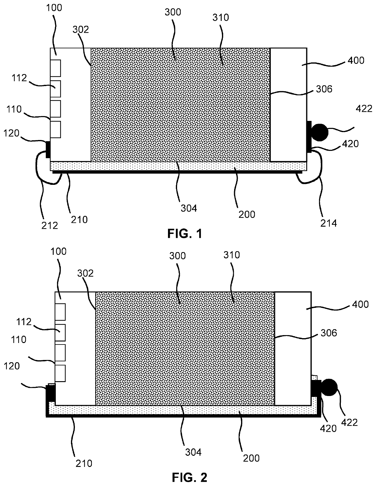
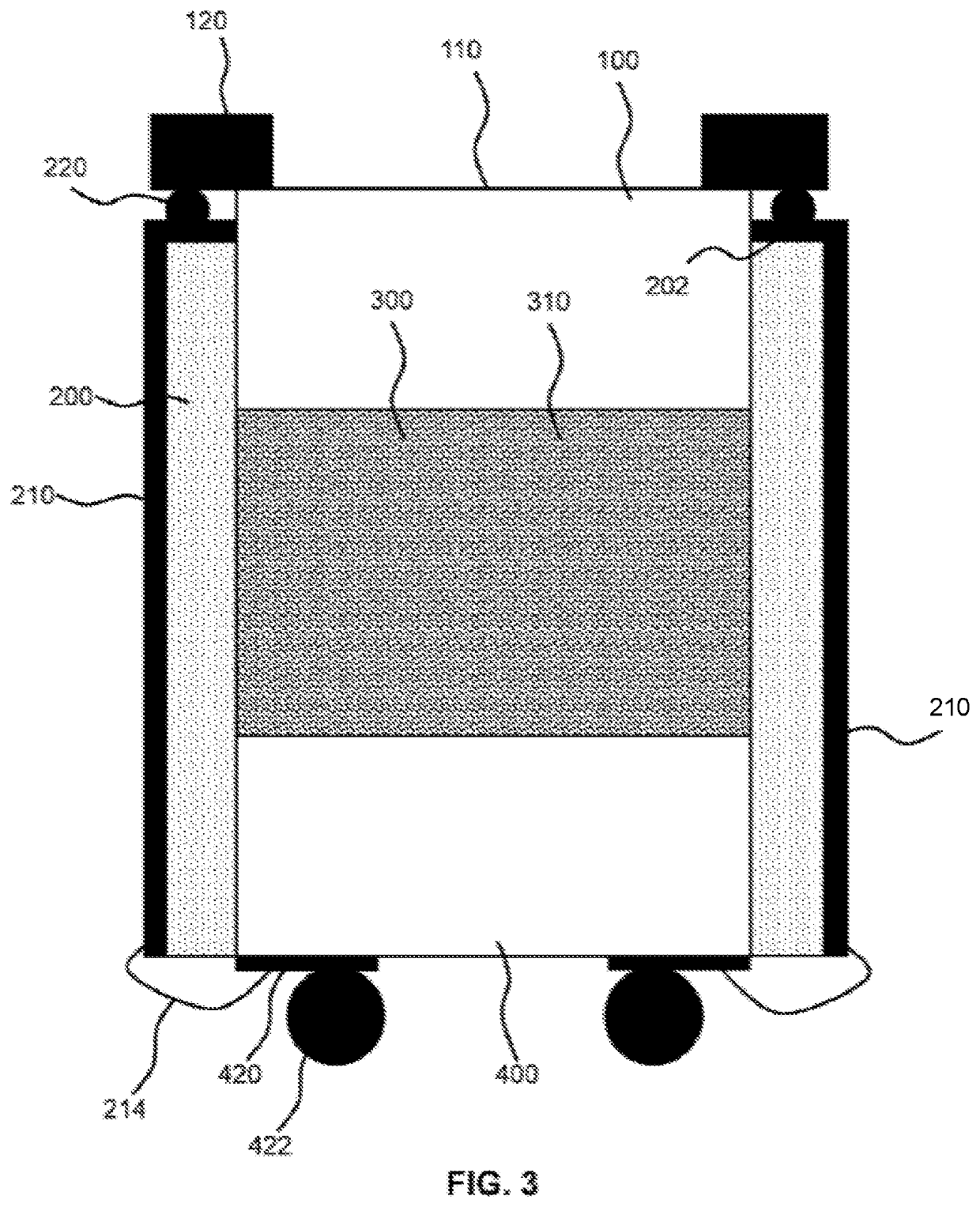
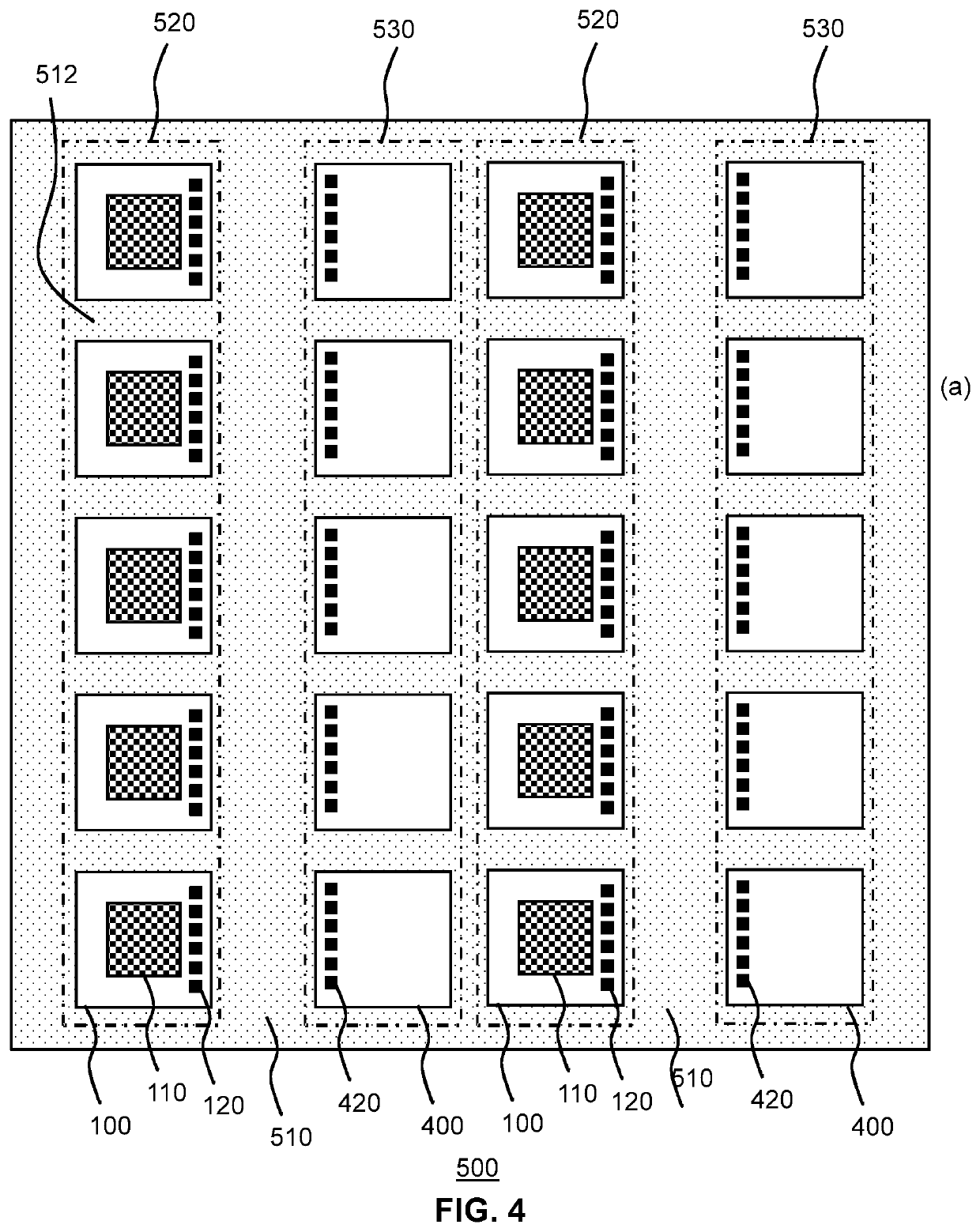
[0040]FIG. 1 schematically depicts an ultrasonic transducer assembly according to an embodiment of the present invention. The assembly comprises an ultrasonic transducer chip 100 having a major surface comprising an ultrasound transducer area 110, which typically comprises a plurality of transducer elements 112, such as CMUT or PZT elements. In a preferred embodiment, the major surface comprises an ultrasound transducer area 110 formed by a plurality of CMUT elements 112. The major surface further comprises a plurality of contacts 120, which may provide points of contact to the transducer elements 112 in any suitable manner as is well-known per se. Any suitable embodiment of such a transducer chip 100 may be chosen; it should be understood that embodiments of...


PUM


Abstract

Disclosed is an ultrasonic transducer assembly comprising an ultrasonic transducer chip (100) having a main surface comprising a plurality of ultrasound transducer elements (112) and a plurality of first contacts (120) for connecting to said ultrasound transducer elements; a contact chip (400) having a further main surface comprising a plurality of second contacts (420); an backing member (300) comprising ultrasound absorbing and / or scattering bodies (310), said backing member comprising a first surface (302) on which the transducer chip is mounted and a second surface (306) on which the contact chip is mounted; and a flexible interconnect (200) extending over said backing member from the main surface to the further main surface, the flexible interconnect comprising a plurality of conductive tracks (210), each conductive track connecting one of said first contacts to a second contact. An ultrasound probe including such an assembly, an ultrasonic imaging system including such an ultrasound probes and manufacturing methods of such an assembly and probe are also disclosed.

Description

[0001]This application is the U.S. National Phase application under 35 U.S.C. § 371 of International Application No. PCT / EP2015 / 059769, filed on May 5, 2015, which claims the benefit of European Application Serial No. 14167101.6, filed May 6, 2014. These applications are hereby incorporated by reference herein.FIELD OF THE INVENTION[0002]The present invention relates to an ultrasonic transducer assembly including an ultrasonic transducer chip and a flexible interconnect to the ultrasonic transducer chip.[0003]The present invention further relates to an ultrasound probe including such an ultrasonic transducer assembly.[0004]The present invention yet further relates to an ultrasonic imaging system comprising such an ultrasound probe.[0005]The present invention still further relates to a method of manufacturing such an ultrasonic transducer assembly.[0006]The present invention still further relates to a method of manufacturing such an ultrasound probe.BACKGROUND OF THE INVENTION[0007]I...

Claims


Application Information

Patent Timeline
Patent Type & Authority Patents(United States)
IPC IPC(8): H01L41/047A61B8/00G10K11/00B06B1/06H01L41/293H01L41/113H10N30/063H10N30/30H10N30/87
CPCB06B1/0622H01L41/0472H01L41/293G10K11/002H01L41/1132A61B8/4483A61B8/0883A61B8/0891A61B8/12A61B8/4494H10N30/063H10N30/302H10N30/872
Inventor WEEKAMP, JOHANNES WILHELMUSHENNEKEN, VINCENT ADRIANUSGROENLAND, ALFONS WOUTERLOUWERSE, MARCUS CORNELIS
Owner KONINKLJIJKE PHILIPS NV
Learn More