Supercharge Your Innovation With Domain-Expert AI Agents!

Print head, liquid ejection apparatus, and piezoelectric element control circuit

a control circuit and liquid ejection technology, applied in the field of printing heads, can solve the problems of unintentional displacement of piezoelectric elements, unintentional bending of vibration plates, and unstable electrical potential of upper electrodes

Active Publication Date: 2020-11-03
SEIKO EPSON CORP
View PDF22 Cites 0 Cited by
  • Summary
  • Abstract
  • Description
  • Claims
  • Application Information

AI Technical Summary

Problems solved by technology

However, in actuality, a leakage current of the switch circuit or exogenous noise or the like accumulates electric charges in the upper electrode of the piezoelectric element.
The electric potential of the upper electrode is likely to be unstable.
Consequently, the piezoelectric element may be unintentionally displaced.
Consequently, the vibration plate is unintentionally bent, and unintended stress is exerted on the vibration plate.
In a case where such unintended stress occurring in the vibration plate is continuously exerted for a long time, stress is concentrated around a contact point between the vibration plate and the cavity, and a crack or the like may occur in the vibration plate.
Consequently, a crack or the like may occur in the vibration plate.
Consequently, the accuracy of ink ejection deteriorates.
That is, not only the accuracy of ejection from the nozzle corresponding to the vibration plate having the crack is affected, but also the accuracy of ink ejection in the whole liquid ejection apparatus may be affected.

Method used


Image

  • Print head, liquid ejection apparatus, and piezoelectric element control circuit
  • Print head, liquid ejection apparatus, and piezoelectric element control circuit
  • Print head, liquid ejection apparatus, and piezoelectric element control circuit

Examples


modification example

7 Modification Example

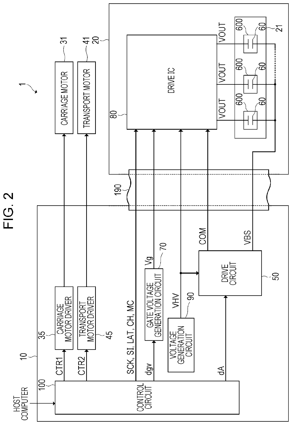
[0193]While a serial scan type (serial printing type) ink jet printer that performs printing on the medium P by moving the print head 20 is illustrated as the liquid ejection apparatus in the embodiment, the invention can also be applied to a line head type ink jet printer that performs printing on a printing medium without moving a head.

[0194]The invention includes substantially the same configuration as the configuration described in the embodiment (for example, a configuration having the same function, the same method, and the same result or a configuration having the same advantage and the same effect). The invention also includes a configuration acquired by replacing a non-substantial part of the configuration described in the embodiment. The invention also includes a configuration that accomplishes the same effect or achieves the same advantage as the configuration described in the embodiment. The invention also includes a configuration acquired by adding...


PUM

PropertyMeasurementUnit
voltageaaaaaaaaaa
voltageaaaaaaaaaa
thicknessaaaaaaaaaa

Abstract

A print head includes a piezoelectric element that includes a first electrode supplied with a drive signal and a second electrode supplied with a reference voltage signal and is displaced by a difference in electric potential between the first electrode and the second electrode, a cavity that is filled with a liquid ejected from a nozzle along with the displacement of the piezoelectric element, a vibration plate that is disposed between the cavity and the piezoelectric element, a gate circuit that is electrically connected to a ground, a first switch circuit that switches between supplying and not supplying the drive signal to the first electrode, and a second switch circuit that switches between electrically connecting and not electrically connecting the gate circuit and the first electrode.

Description

[0001]This application claims priority to Japanese Patent Application No. 2018-057649 filed on Mar. 26, 2018. The entire disclosure of Japanese Patent Application No. 2018-057649 is hereby incorporated herein by reference.BACKGROUND1. Technical Field[0002]The present invention relates to a print head, a liquid ejection apparatus, and a piezoelectric element control circuit.2. Related Art[0003]In an ink jet printer (liquid ejection apparatus) that prints an image or a document by ejecting a liquid such as ink, it is known that a piezoelectric element such as a piezo element is used as a drive element. The piezoelectric element is disposed in a print head in correspondence with a plurality of nozzles ejecting ink and a cavity retaining ink ejected from the nozzle. By displacing the piezoelectric element in accordance with a drive signal, a vibration plate disposed between the piezoelectric element and the cavity is bent, and the capacity of the cavity is changed. Accordingly, a predet...

Claims


Application Information

Patent Timeline
Patent Type & Authority Patents(United States)
IPC IPC(8): B41J2/045B41J2/14
CPCB41J2/04541B41J2/14201B41J2/0455B41J2/04588B41J2/04581B41J2002/14491B41J2/04551B41J2/04593B41J2/04596
Inventor YAMADA, TOMOKAZUCHIKAMOTO, MOTONORI
Owner SEIKO EPSON CORP
Features
  • R&D
  • Intellectual Property
  • Life Sciences
  • Materials
  • Tech Scout
  • Unparalleled Data Quality
  • Higher Quality Content
  • 60% Fewer Hallucinations
Learn More