Electroporation electrode configuration and methods
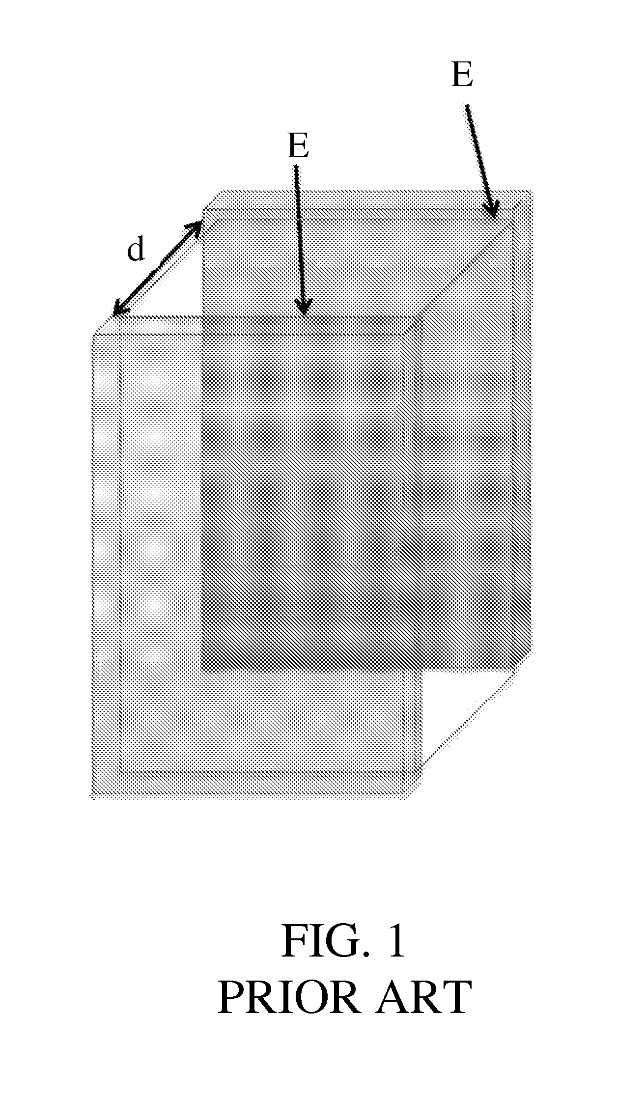
a technology of electroporation electrodes and configuration methods, applied in the field of electroporation electrode configuration and methods, can solve the problems of large potential differences between electrodes, high potential differences across electroporation electrodes, and formation of transient or permanent pores, and achieve low potential differences and high electric fields.
- Summary
- Abstract
- Description
- Claims
- Application Information
AI Technical Summary
Benefits of technology
Problems solved by technology
Method used
Image
Examples
example 1
Nomenclature for Example 1
[0063]φ=electric potential
φa=electric potential at anode
φc=electric potential at cathode
φdiff=electric potential difference between electrodes
L=active electrode length
H=half of micro-electroporation channel height
r=cell radius
Φ=non-dimensional electric potential
Φa=non-dimensional electric potential at anode
Φc=non-dimensional electric potential at cathode
X=non-dimensional x-coordinate
Y=non-dimensional y-coordinate
A=channel aspect ratio
R=relative cell radius
E=non-dimensional electric field
T=temperature
Qgen=volumetric heat generation
ρ=density
Cp=specific heat at constant pressure
u=x-velocity
σ=electrical conductivity
μ=dynamic viscosity
p=pressure
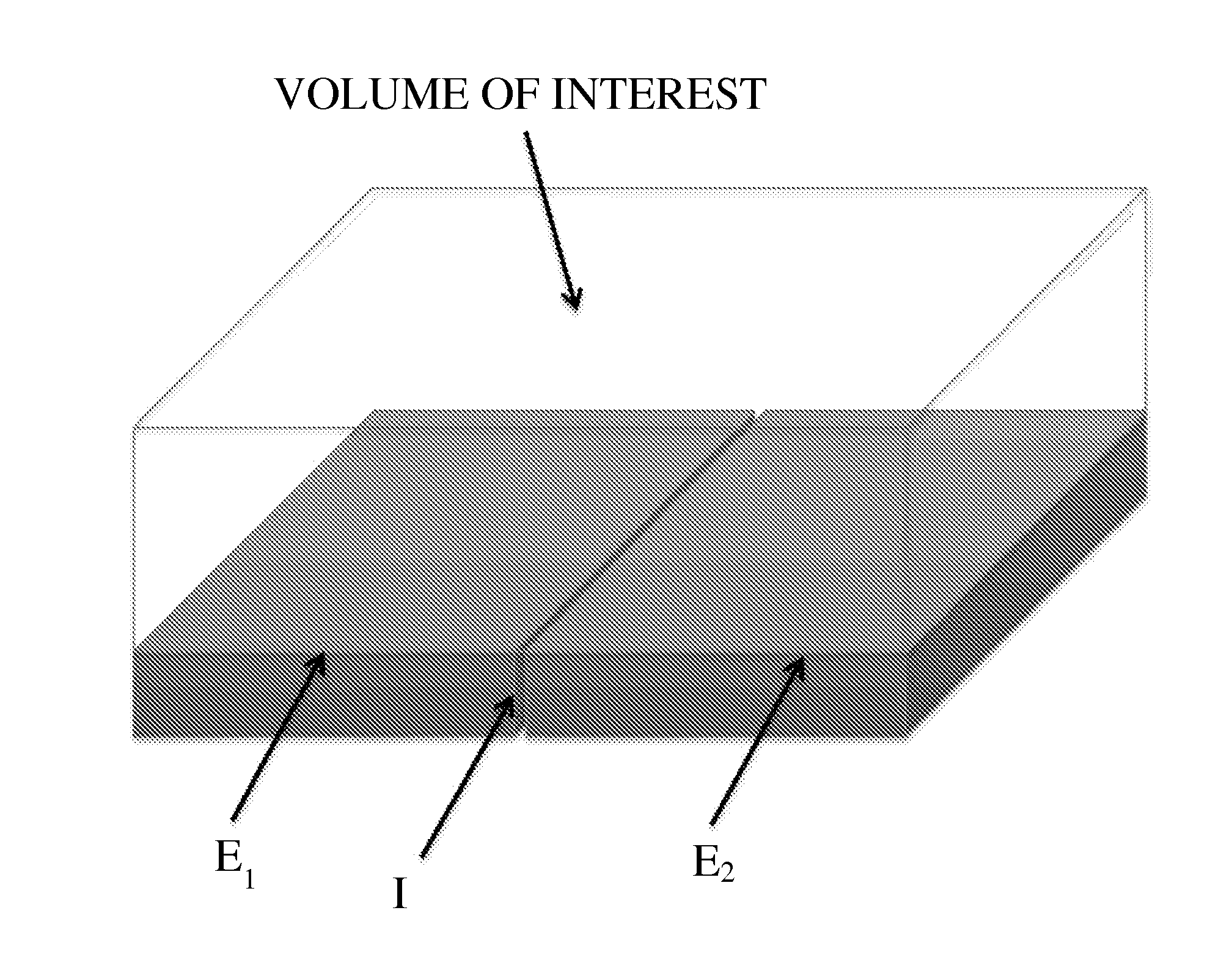
[0064]FIG. 4(a) is a schematic of the micro-electroporation channel configuration. FIG. 4(b) illustrates a model domain in the absence of a cell. FIG. 4(c) illustrates a model domain in the presence of a cell. FIG. 5 shows radially-varying electric fields generated in the micro-electroporation channe...
example 2
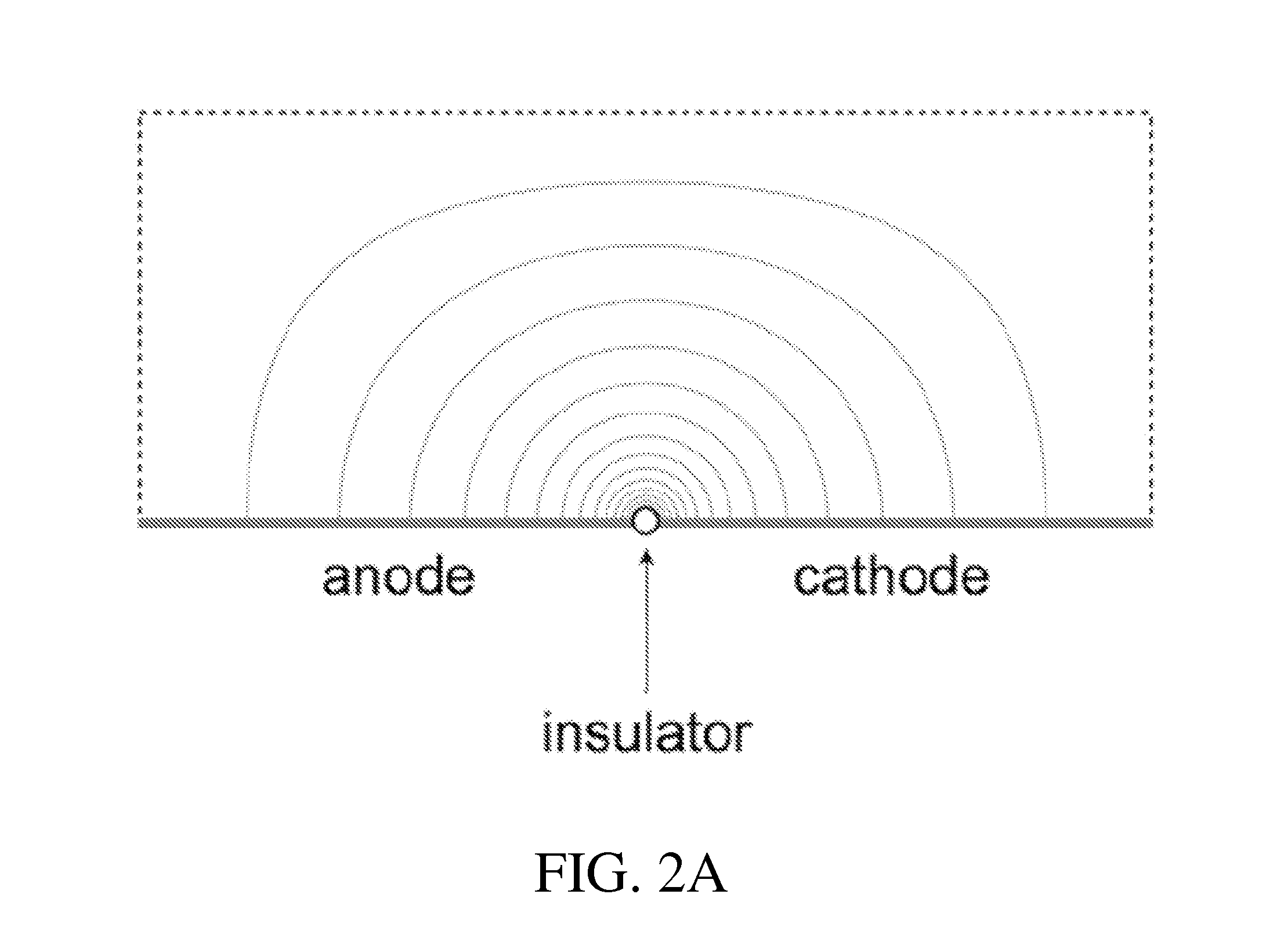
[0081]The theoretical highest electric field can be produced in the configuration discussed in this invention when the dimension of the insulating singularity between the voltage sources tends to limit of zero. We have used the same methodology of analysis to evaluate what is the effect of the insulating gap thickness on the electric field produced. The results show that a technologically achievable 100 nanometer gap can produce the desired effects.
[0082]The models were done in a similar way to those described in the previous example with non-dimensional insulation lengths varying from 0.01 to 0.1 (insulation length / domain length) for an aspect ratio of 0.1. The non-dimensional insulation length can be scaled to the domain height by dividing by the aspect ratio. FIG. 14 is a plot that shows the non-dimensional electric field (EF) strength at X=0.5, for different insulation thicknesses. In other words, FIG. 14 shows the electric field as a function of height Y from the surface at the...
example 3
[0085]This example is similar to the Example 1 and Example 2. However, Example 3 introduces a new concept. Because the voltage difference across the insulator can be very small, it can be also produced through electrolysis between two dissimilar metals separated by the insulator and brought in electric contact through the electrical conductive media. This configuration may allow for the unprecedented miniaturization of single-cell micro-electroporation devices and micro-batteries. Furthermore, while each application is independent, by combining them, it is possible to perform single-cell micro-electroporation with no power input, through electrolysis. In the process, it is even possible to produce electric power.
[0086]Electrochemical cells are devices capable of delivering electrical energy from chemical reactions (galvanic cells), or conversely, facilitating chemical reactions from the input of electrical energy (electrolytic cells). All electrochemical cells are composed of at lea...
PUM
| Property | Measurement | Unit |
|---|---|---|
| Length | aaaaa | aaaaa |
| Length | aaaaa | aaaaa |
| Nanoscale particle size | aaaaa | aaaaa |
Abstract
Description
Claims
Application Information
 - R&D
- Intellectual Property
- Life Sciences
- Materials
- Tech Scout
- Unparalleled Data Quality
- Higher Quality Content
- 60% Fewer Hallucinations
Browse by: Latest US Patents, China's latest patents, Technical Efficacy Thesaurus, Application Domain, Technology Topic, Popular Technical Reports.
© 2025 PatSnap. All rights reserved.Legal|Privacy policy|Modern Slavery Act Transparency Statement|Sitemap|About US| Contact US: help@patsnap.com


