Electrical storage device and manufacturing electrical storage device

Inactive Publication Date: 2006-03-16
FUJI JUKOGYO KK
View PDF8 Cites 117 Cited by
  • Summary
  • Abstract
  • Description
  • Claims
  • Application Information

AI Technical Summary

Benefits of technology

[0130] A voltage when the voltage of the cell is increased until the electrolyte is oxidized and dissolved is determined almost by the potential of the positive electrode. Compared to a capacitor having the typical cell arrangement, the capacitor of the present invention having the lithium ion carried in advance has a higher breakdown voltage, but this is due to the low potential of the negative electrode. That is, while the use voltage of the conventional capacitor is in a range of about 2.3 to 2.7 V, the arrangement of the present invention may be in as high as more than 3 V, thus improving energy density.
[0131] Further, as the third effect, the potential of the positive electrode is lowered, and thus, the capacity of the positive electrode can be increased. With a lowered potential of the negative electrode, the amount of the potential change while charging is conducted at the positive electrode can

Problems solved by technology

For example, when the negative electrode lithium ion is carried, conventionally, the lithium electrode and the negative electrode arranged in the cell are electrochemically contact so that the carry of lithium ion is initiated at the time of injecting electrolyte, and thus there occurs a problem in that non-uniform of the carry is generated between a portion that the lithi

Method used


Image

  • Electrical storage device and manufacturing electrical storage device
  • Electrical storage device and manufacturing electrical storage device
  • Electrical storage device and manufacturing electrical storage device

Examples


first embodiment

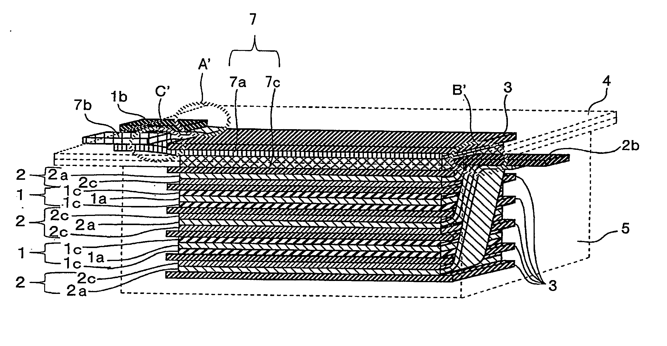
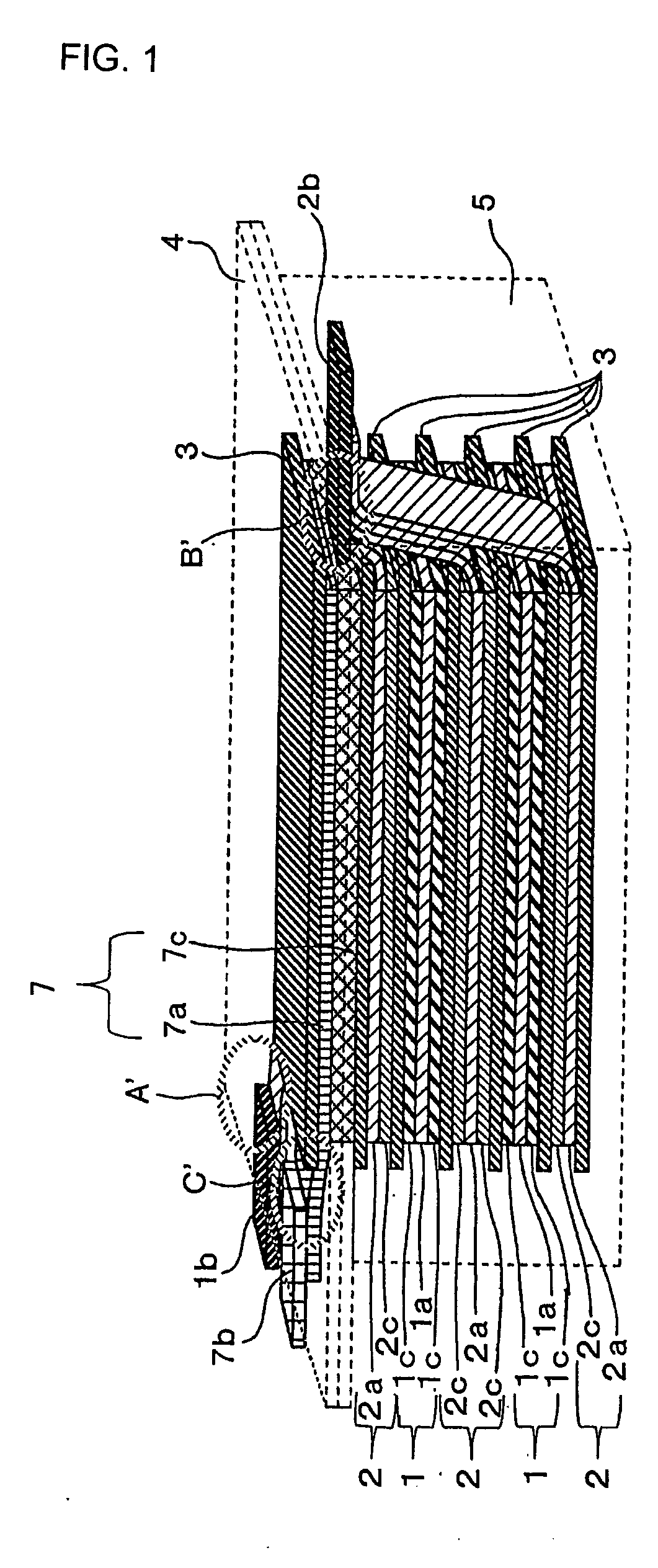
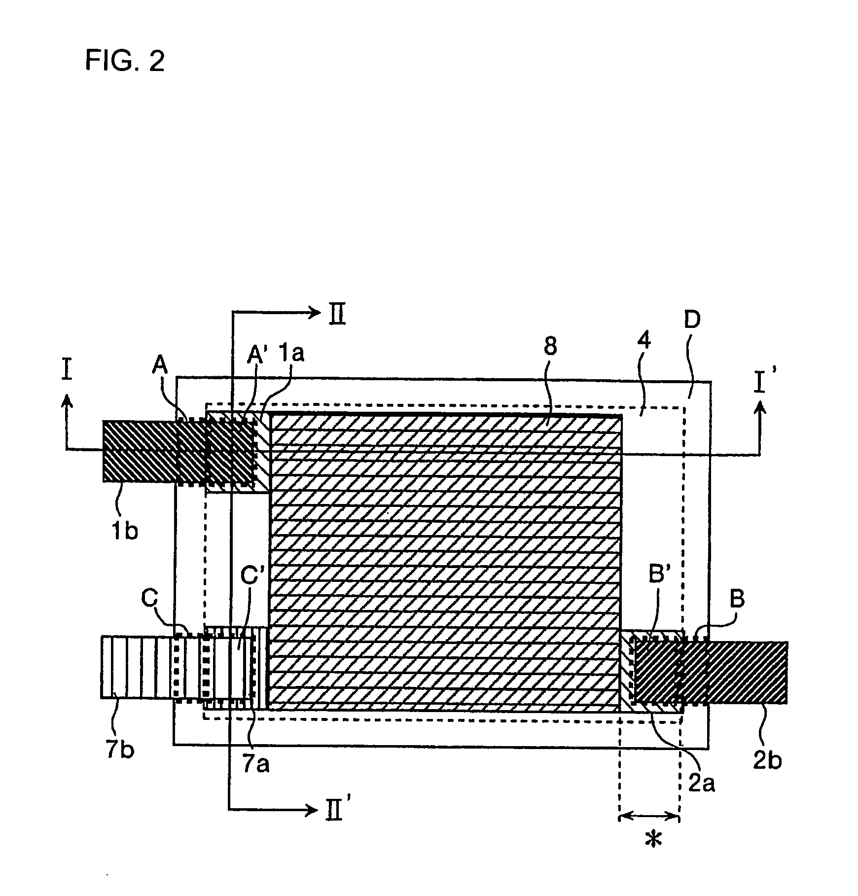
[0152]FIG. 1 is a perspective view of a first embodiment of the present invention; FIG. 2 is a plan view of a first embodiment of the present invention; FIG. 3 is a cross-sectional view taken along I-I′ of FIG. 2; and FIG. 4 is a cross-sectional view taken along II-II′ of FIG. 2.

[0153] In the first embodiment, a lithium electrode 7 is arranged on an electrode stack unit 6, in which an electrode couple including a positive electrode 1 and a negative electrode 2 are stacked one after another so as to form a three-electrode stack unit 8.

[0154] In the first embodiment, three sheets of negative electrode collector 2a, and two sheets of positive electrode collector la are used to form the electrode stack unit 6. The electrode stack unit 6 includes separators 3 between the positive electrodes and the negative electrodes in order to prevent direct contact between the positive and negative electrodes. Also, from the lower layer, there are stacked a first negative electrode collector 2a hav...

second embodiment

[0165] The second embodiment will now be described. FIG. 8 is a plan view of the second embodiment. The second embodiment has the same arrangement as in the first embodiment except that three-electrode external terminals are protruded at the same side.

[0166] Like numbers between the first and second embodiments refer to like elements, so that only different portions will be described in detail. Referring to the second embodiment, the positive electrode terminal 1b, the negative electrode terminal 2b, and the lithium electrode terminal 7b are protruded out of the same side. When the laminated film has the same size, the electrode size can be made large with the positive electrode terminal 1b, the negative electrode terminal 2b and the lithium electrode terminal 7b, so that a capacity is preferably increased. Comparing the first embodiment where the positive electrode terminal 1b, the lithium electrode terminal 7b, and the negative electrode terminal 2b are protruded at the opposite ...

third embodiment

[0167] The third embodiment will now be described. FIG. 9 is a plan view of the third embodiment. The third embodiment involves a plan view of a capacitor having an arrangement in which the plate type lithium electrode is rolled into the center. FIG. 10 is a cross-sectional view taken along an I-I′ line of FIG. 9, and FIG. 11 is a cross-sectional view of II-II′ line of FIG. 9. Like numbers between the first and third embodiments refer to like elements, so that only different portions will be described in detail.

[0168] In the third embodiment, the plate type lithium electrode 7 is rolled into the center as shown in FIG. 10. The lithium electrode 7 is formed on both surfaces of the lithium electrode collector 7a. The positive electrode 1 and the negative electrode 2 are formed on one surface of the ribbon type positive electrode collector 1a and negative electrode collector 2a, respectively. With a center of the lithium electrode collector 7a having the lithium electrode 7 arranged o...


PUM

PropertyMeasurementUnit
Weightaaaaaaaaaa
Ratioaaaaaaaaaa
Electrical conductoraaaaaaaaaa

Abstract

An electrical storage device of the present invention is characterized in that a positive electrode, a negative electrode, a lithium electrode, and an electrolyte capable of transferring lithium ion is included, the lithium electrode is arranged to be out of direct contact with the negative electrode, and lithium ion can be supplied to the negative electrode by flowing a current between the lithium electrode and the negative electrode through an external circuit. With the above characteristic, problems such as non-uniform carrying of lithium ion to the negative electrode, shape-change of a cell, and temperature increase of an electrolytic solution under incomplete sealing of a cell and the like can be easily solved. A using method of the electrical storage device is characterized in that, by using the lithium electrode as a reference electrode, the positive electrode potential and negative electrode potential can be measured, and the potential of the positive or negative electrode can be controlled when the electrical storage device is charged or discharged. Therefore, the potentials of the positive electrode and negative electrode can be monitored, thereby it can be easily determined whether deterioration of the electrical storage device is caused by the positive electrode or the negative electrode. Also, it is possible to control the device with the potential difference between the negative electrode and reference electrode, that is, the negative potential. In addition, when characteristics deteriorate such as the internal resistance increase, an appropriate amount of lithium ion can be supplied to the negative electrode and/or positive electrode by the lithium electrode.

Description

TECHNICAL FIELD [0001] The present invention relates to an electrical storage device and a manufacturing method of an electrical storage device capable of readily preventing non-uniform carrying when lithium ions are carried to a negative electrode, and shape-changing of a negative electrode. BACKGROUND ART [0002] Recently, with a high energy concentration, a secondary battery having a positive electrode such as a conductive polymer and a transition metal oxide and a negative electrode such as a lithium metal or a lithium alloy (hereinafter, briefly referred to as a lithium metal) has been proposed to replace a Ni—Cd battery and a lead battery. However, when charging and discharging are repeatedly performed, this secondary battery is subject to large, reduction of capacity due to degradation of the positive electrode or the negative electrode, and thus there remains a practical problem. In particular, degradation of the negative electrode leads to generation a mossy lithium crystal ...

Claims


Application Information

Patent Timeline
IPC IPC(8): H01M14/00H01M4/58H01M10/04H01G11/06H01G11/22H01G11/24H01G11/30H01G11/38H01G11/46H01G11/48H01G11/50H01G11/60H01G11/62H01G11/70H01G11/78H01G11/86H01M4/13H01M6/50H01M10/052H01M10/058H01M10/0587H01M10/36H01M10/42H01M10/44H01M10/48
CPCH01G9/155Y10T29/49108H01M4/382H01M4/587H01M6/5005H01M6/5044H01M10/0431H01M10/0436H01M10/052H01M10/058H01M10/0587H01M10/4242H01M10/44H01M10/446H01M10/48H01M2010/4292Y02E60/122Y02E60/13Y02T10/7011Y02T10/7022Y10T29/4911H01M4/13Y02T10/70Y02E60/10Y02P70/50H01G11/14H01G11/50H01G11/06H01G11/00H01G11/58H01G11/26H01G11/74
Inventor ANDO, NOBUOTASAKI, SHINICHIHATO, YUKINORIMARUMO, CHISATO
Owner FUJI JUKOGYO KK
Why Eureka
Try Eureka