Self-cooled reactor apparatus

a self-cooled, reactor technology, applied in the direction of locomotives, electric devices, transportation and packaging, etc., can solve the problems of increased maintenance work and increased noise, and achieve the effect of maintaining cooling performan

Active Publication Date: 2020-11-03
MITSUBISHI ELECTRIC CORP
View PDF16 Cites 1 Cited by
  • Summary
  • Abstract
  • Description
  • Claims
  • Application Information

AI Technical Summary

Benefits of technology

[0008]According to the present disclosure, the protective member is provided that, while retaining a flow passage for air from the through-hole to the coil, blocks the space between the through-hole and the coil in the penetration direction of the through-hole, thereby enabling protection of the coil while maintaining cooling performance.

Problems solved by technology

When an air blower is provided to cool the coil in order to suppress the rise in temperature of the coil, problems occur such as increased maintenance work due to added of the air blower and increased noise due to the electric motor used in the air blower.

Method used


Image

  • Self-cooled reactor apparatus
  • Self-cooled reactor apparatus
  • Self-cooled reactor apparatus

Examples


Embodiment Construction

[0018]Embodiments of the present disclosure are described below in detail in reference to drawings. In the drawings, components that are the same or equivalent are assigned the same reference signs.

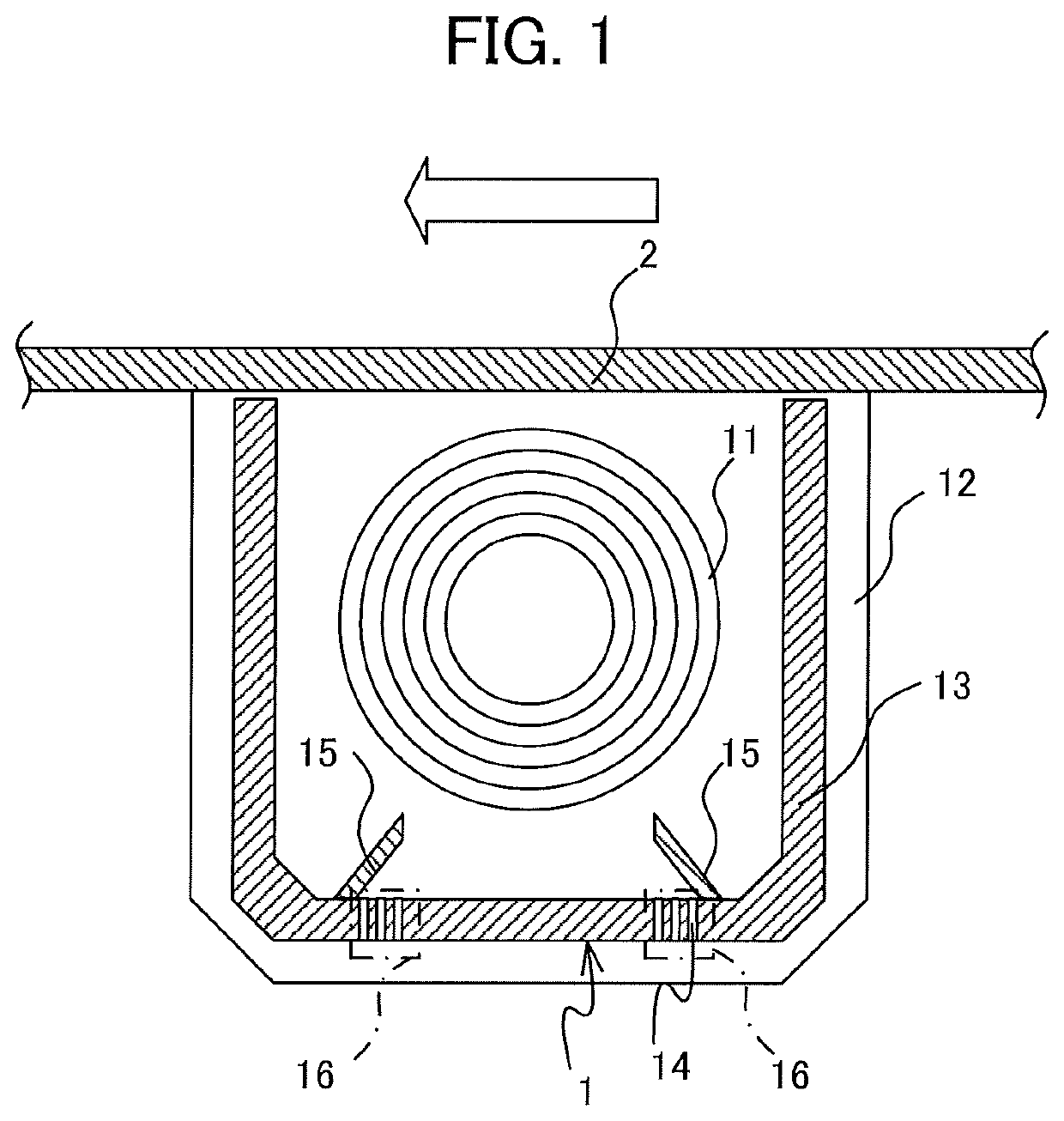
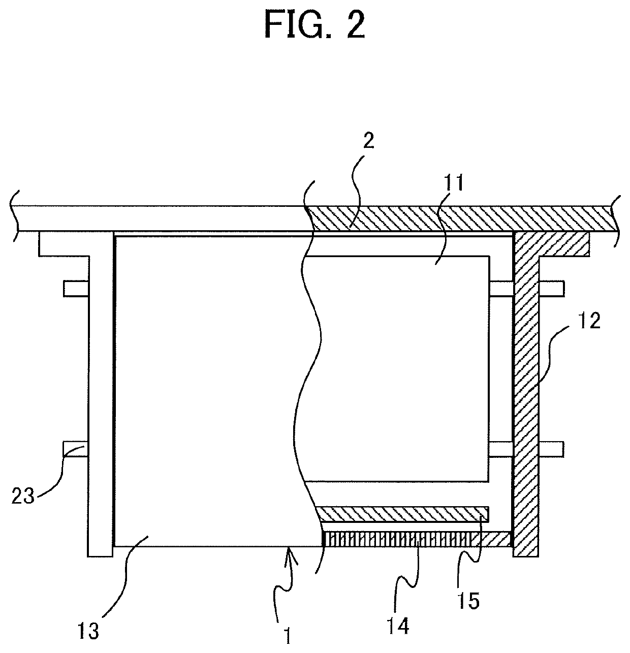
[0019]FIG. 1 is a cross-sectional view of a self-cooled reactor apparatus according to an embodiment of the present disclosure. A self-cooled reactor apparatus 1 is arranged above the roof or under the floor of a vehicle. FIG. 1 is a cross-sectional view taken along a travel direction of the vehicle. In the example of FIG. 1, the self-cooled reactor apparatus 1 is attached to a lower surface of a vehicular mount 2 under the floor of the vehicle. The outlined-type arrow symbol in FIG. 1 indicates the direction of travel of the vehicle. FIG. 2 is a partial cross-sectional view of the self-cooled reactor apparatus according to the embodiment. FIG. 2 is a view of the self-cooled reactor apparatus 1 as seen from the direction of travel of the vehicle. The coil 11 included in the self-cooled re...


PUM

PropertyMeasurementUnit
thickaaaaaaaaaa
temperatureaaaaaaaaaa
shapeaaaaaaaaaa

Abstract

A self-cooled reactor apparatus includes: a pair of frames attached to a vehicular mount, a coil disposed between the pair of frames and fixed to the frames, a cover disposed between the pair of frames, and a protective member. The coil is covered by the cover having at least a portion thereof in which through-holes are formed. The protective member, while retaining a flow passage for air from the through-holes to the coil, blocks a space between the through-hole and the coil in a penetration direction of the through-holes.

Description

TECHNICAL FIELD[0001]The present disclosure relates to a self-cooled reactor apparatus mounted on a vehicle and cooled by traveling airflow.BACKGROUND ART[0002]A reactor apparatus is mounted above the roof or under the floor of a railway vehicle. The reactor apparatus has a coil for suppression of large changes in electric current, and the coil is used to suppress changes in, for example, a high frequency switching current, a ground fault current, or the like. Temperature of the coil rises when heat of resistance is generated by current flowing through the coil. When an air blower is provided to cool the coil in order to suppress the rise in temperature of the coil, problems occur such as increased maintenance work due to added of the air blower and increased noise due to the electric motor used in the air blower. Thus self-cooled reactor apparatuses are widely used that do not use an air blower.[0003]The coil is cooled by air convection in the case of the self-cooled reactor appara...

Claims


Application Information

Patent Timeline
Patent Type & Authority Patents(United States)
IPC IPC(8): H01F27/02H01F27/08B60L3/00H05K7/20B60K11/06B61C17/00B60L9/00H01F37/00H01F27/28
CPCB61C17/00H01F27/085H05K7/20H01F27/025H01F27/08B60L9/005B60K11/06H01F37/00B60L3/00H01F27/28
Inventor INABA, SATOSHIISHIMORI, YUKI
Owner MITSUBISHI ELECTRIC CORP
Why Eureka
Try Eureka