
Novel rotary shaft assembly

a technology of rotary shaft and rotor shaft, which is applied in the direction of friction clutches, interengaging clutches, and friction clutches, can solve the problems of low fuel efficiency, torque short transfer into the transmission, and low preference in south korea and north america, so as to prevent sudden unintended acceleration, accurate and permanent use, and simplify transmission

Pending Publication Date: 2022-05-19
AUTODYN SYS INC
View PDF4 Cites 4 Cited by
  • Summary
  • Abstract
  • Description
  • Claims
  • Application Information

AI Technical Summary

Benefits of technology

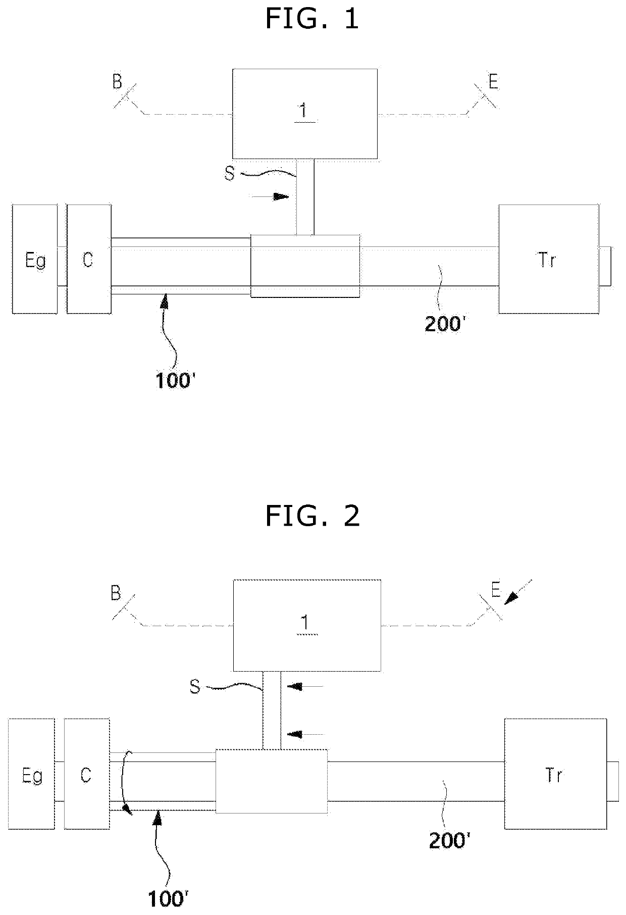
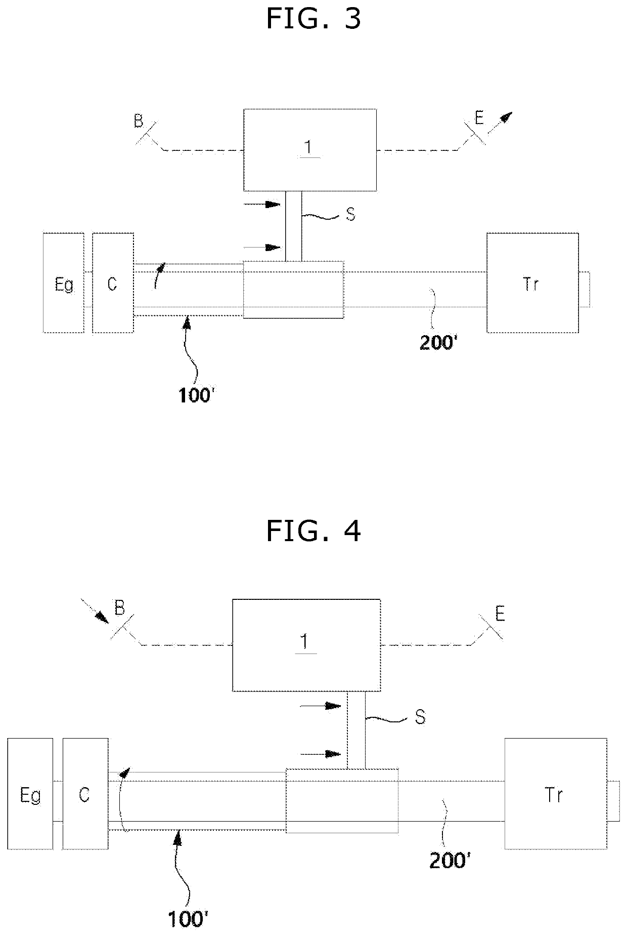
The rotary shaft assembly of this patent can be used in manual transmission vehicles and is designed to expand the base of these vehicles with simplified transmissions. It is also designed to prevent sudden unintended acceleration and protect drivers and pedestrians from injury. The assembly can be used in all vehicles and is particularly useful in hybrid cars. In additional, it can be used in electric vehicles and other power plants that use internal combustion engines.

Problems solved by technology

In case of automatic transmission vehicles, they have to be switched in conjunction with the clutch pedal at the same time; thus, there is a low preference in South Korea and North America due to slipping when re-starting on ramps.
In case of automatic transmission vehicles, they have a low fuel efficiency due to the torque transmission through fluid, and are vulnerable to a torque short that is transferred into the transmission from the engine in the abnormal event such as a sudden unintended acceleration.

Method used


Image

  • Novel rotary shaft assembly
  • Novel rotary shaft assembly
  • Novel rotary shaft assembly

Examples


Embodiment Construction

Technical Problems

[0010]Accordingly, the present invention is suggested to provide a rotary shaft assembly applied to a novel clutch system, which ensures a 100% torque transmission rate between an engine and a transmission in a vehicle system and can be commonly applied to conventional manual transmission and automatic devices.

Summary of the Invention

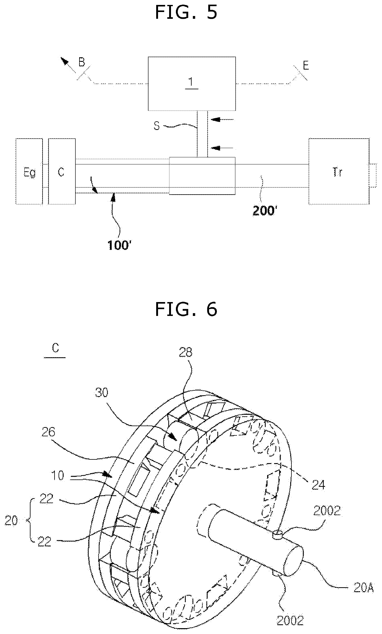
[0011]To solve the problems mentioned above, the present invention provides a rotary shaft assembly converting linear motion of a driving shaft to rotary motion of a rotatable cam of a clutch assembly, wherein the driving shaft linearly moves according to pressing or releasing of an accelerator pedal or brake pedal, wherein at least one of protrusion is formed in a sleeve of a rotary shaft of the cam, wherein at least one of guide slot is formed on the driving shaft to receive the protrusion, respectively, wherein the guide slot includes: a first path having a linear shape, and a second path extending to form an inclined angle with the...


PUM


Abstract

The present invention provides a rotary shaft assembly applied to a novel clutch system that ensures a 100% torque transmission rate between an engine and a transmission in a vehicle system and can be commonly applied to conventional manual transmission vehicles and automatic vehicles. The rotary shaft assembly converts linear motion of one member to rotary motion of another member, using a combination of a protrusion and an inclined guide slot.

Description

FIELD OF THE INVENTION[0001]Applicant of the present invention suggested a connection part transmitting a driving force of a power transmission device to a clutch device, in Korean Application No. 10-2019-0128511 filed on Oct. 16, 2019. The connection part is applied to a clutch system comprising a power transmission device interlocking with an accelerator and brake pedal, which is disclosed in another Korean Application No. 10-2019-0166488 filed on Dec. 13, 2019.[0002]In Korean Application No. 10-2020-0034811 filed on Mar. 23, 2020, applicant suggested a clutch assembly comprising an out-cam rotating in one direction or the other direction according to pressing or releasing of an accelerator or brake pedal, and a forked part supporting a rotary member that comes in contact with the out-cam.[0003]The present invention relates to a novel rotary shaft assembly that is improved from an invention in Korean Application No. 10-2019-0128511. More specifically, the present invention provide...

Claims


Application Information

Patent Timeline
Patent Type & Authority Applications(United States)
IPC IPC(8): F16D23/14
CPCF16D23/14F16D2023/123F16D2023/141F16D15/00F16D23/12F16D13/02F16D11/02F16D11/08F16D13/025F16D2011/002F16D2011/004F16H25/186F16H25/12
Inventor YOON, JONGYUN
Owner AUTODYN SYS INC
Learn More