Pressure bulkhead system

a bulkhead and pressure technology, applied in the direction of fuselage bulkheads, fuselage frames, fuselage bulkheads, etc., can solve the problem that the dome shape occupies valuable space in the cabin, and achieve the effect of reducing the stress acting

Active Publication Date: 2020-11-03
AIRBUS OPERATIONS GMBH
View PDF7 Cites 0 Cited by
  • Summary
  • Abstract
  • Description
  • Claims
  • Application Information

AI Technical Summary

Benefits of technology

[0005]The invention is directed to an object of providing a pressure bulkhead system comprising a peripheral pressure frame for sealingly connecting a pressure bulkhead to a fuselage of a vehicle in order to separate a pressurized cabin space from an unpressurized cabin space of the vehicle, wherein the peripheral pressure frame is capable of deforming, to a certain extent, in response to a cabin pressure load acting on the pressure bulkhead and to thus reduce the stresses acting on the peripheral pressure frame and, in particular, to a connection of the peripheral pressure frame to a structural component of the vehicle. Further, the invention is directed to an object of providing a vehicle which is equipped with a pressure bulkhead system of this kind, and a method for mounting a pressure bulkhead system of this kind in a vehicle.
[0011]Thus, the pressure bulkhead system is designed in such a manner that the peripheral pressure frame, when the pressure bulkhead system is installed in the vehicle, is capable of deforming to a certain extent in response to a cabin pressure load acting on the pressure bulkhead and to thus reduce the stresses acting on the peripheral pressure frame and, in particular, to a connection of the peripheral pressure frame to the vehicle fuselage. As a result, a particularly reliable, but still lightweight connection between the pressure bulkheads and the vehicle fuselage can be established.
[0015]For example, the flexible section may incorporate, when viewed in axial cross-section through the pressure bulkhead system, two curves separated by one straight, three curves separated by two straights and so on. The provision of the curved portions in the ring frame leads to a reduction of stresses due to cabin pressure compared with the prior art design of, for example, U.S. Pat. No. 8,596,578 B2. In particular, incorporation of a curved junction reduces the risk of separation of the attachment of the peripheral pressure frame where it is connected to the pressure bulkhead or the vehicle fuselage.
[0017]The pressure bulkhead may be made of a composite material based on a polymer matrix reinforced with fibers. Alternatively or additionally thereto, the peripheral pressure frame may be made of a composite material based on a polymer matrix reinforced with fibers. Making the peripheral pressure frame of composite when the pressure bulkhead is also made of composite is beneficial, because then there is a materials match which eliminates the scope for problems with differential thermal expansion between the peripheral pressure frame and the pressure bulkhead. Providing a pressure bulkhead and / or a peripheral pressure frame made of carbon-fiber reinforced polymer is further advantageous compared with an equivalent metal part, since carbon-fiber reinforced polymer is not associated with fatigue problems. In any case, any differential thermal expansion between the pressure bulkhead and the vehicle fuselage can be accommodated by the peripheral pressure frame's flexible profile, in the same way as cabin pressure is accommodated, thereby avoiding thermally induced stresses.

Problems solved by technology

However, the dome shape takes up valuable space within the cabin.

Method used


Image

  • Pressure bulkhead system
  • Pressure bulkhead system
  • Pressure bulkhead system

Examples


Embodiment Construction

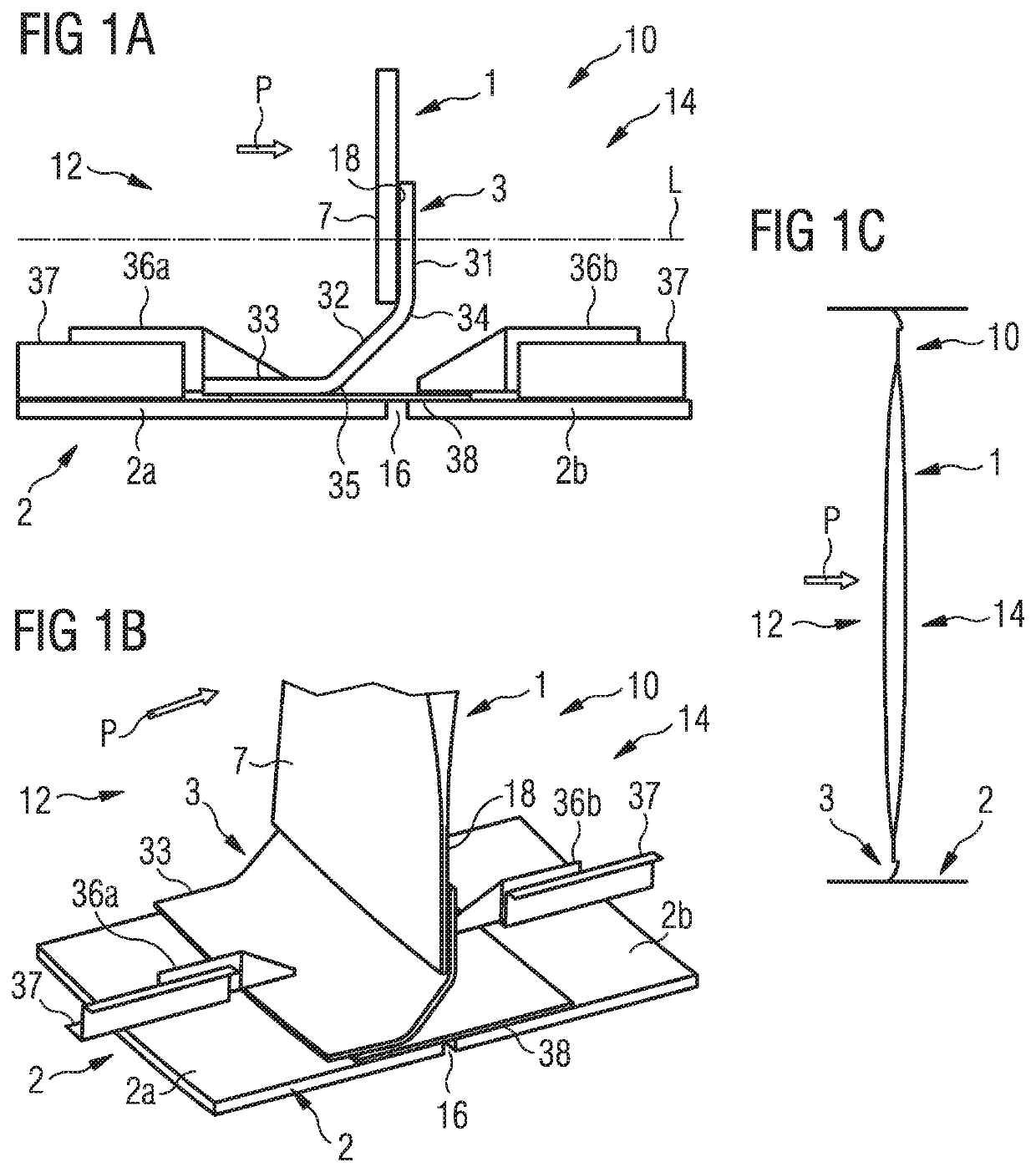
[0034]FIG. 1A is a schematic cross-sectional drawing of a rear pressure bulkhead system 10 according to a first embodiment. FIG. 1B is a schematic perspective view of the same structure. In FIG. 1B, not all of the reference numerals of FIG. 1A are reproduced to avoid cluttering. FIG. 1C is a schematic cross-section of the whole bulkhead system 10 of the first embodiment which is included to show the overall shape of the bulkhead system 10.

[0035]The first embodiment of the pressure bulkhead system 10 is now described with reference to FIGS. 1A, 1B and 1C.

[0036]The direction of action of cabin overpressure is indicated schematically by the arrow ‘P.’ The terms “axial(ly)” and “radial(ly)” make reference to the substantially cylindrical shape of a conventional fuselage, and “outward(ly)” and “inward(ly)” to directions along a radius of the cylinder respectively away from and towards the central axis of the cylinder.

[0037]In a first embodiment, a pressure bulkhead system 10 as depicted ...


PUM


Abstract

A pressure bulkhead system comprises a pressure bulkhead adapted to be connected to a fuselage of a vehicle to separate a pressurized cabin space of the vehicle from an unpressurized cabin space of the vehicle, and a peripheral pressure frame to sealingly connect the pressure bulkhead to the vehicle fuselage. The peripheral pressure frame comprises an attachment section sealingly attached to an outer rim portion of a first surface of the pressure bulkhead. The first surface, when the pressure bulkhead system is installed in the vehicle, faces the unpressurized cabin space of the vehicle. A flange section is adapted to be sealingly attached to an inner surface of the vehicle fuselage and extends in a direction facing away from the first surface of the pressure bulkhead. A flexible section interconnects the attachment section and the flange section and is flexible to accommodate cabin pressure acting on the pressure bulkhead.

Description

CROSS-REFERENCES TO RELATED APPLICATIONS[0001]This application claims the benefit of the European patent application No. 16 169 574.7 filed on May 13, 2016, the entire disclosures of which are incorporated herein by way of reference.BACKGROUND OF THE INVENTION[0002]The present invention relates to a pressure bulkhead system for installation in a vehicle, in particular an aircraft, in order to separate a pressurized cabin space from an unpressurized cabin space. Further, the invention relates to a vehicle, in particular an aircraft, which is equipped with a pressure bulkhead system of this kind, and a method for mounting a pressure bulkhead system of this kind in a vehicle, in particular an aircraft.[0003]Aircraft with pressurized cabins have front and rear pressure bulkheads arranged near the front and rear of the fuselage, respectively. The pressure bulkheads typically have some degree of flexibility so they can deform to accommodate pressure changes within the cabin. Most pressure...

Claims


Application Information

Patent Timeline
Patent Type & Authority Patents(United States)
IPC IPC(8): B64C1/10B64C1/06B64C1/12B64C1/00B64D9/00
CPCB64C1/10B64C1/068B64D9/00B64C2001/009B64C1/12B64C1/061
Inventor GRASE, KARIMSCHIMMLER, MARCEILKEN, WOLFGANGTIRYAKI, MEMIS
Owner AIRBUS OPERATIONS GMBH
Why Eureka
Try Eureka