
Seal for a gas turbine

a gas turbine and seal technology, applied in the direction of engine seals, machines/engines, engine fuctions, etc., can solve the problems of loss or damage to the slim structure, performance penalty, seal life, etc., to reduce minimise the effect of flutter

Active Publication Date: 2020-11-03
ROLLS ROYCE PLC
View PDF12 Cites 0 Cited by
  • Summary
  • Abstract
  • Description
  • Claims
  • Application Information

AI Technical Summary

Benefits of technology

[0013]Material may not be distributed regularly around the circumference of the rotor sealing component. The material of the rotor may form the structure of the rotor. The material of the rotor may be all solid parts of the rotor. The unevenly distributed material may be arranged such that it prevents vibrational modes that cause travelling waves around the circumference of the rotor. The unevenly distributed material may be arranged such that the unevenly distributed material minimises the effects of flutter.
[0020]The balancing masses may be joined or integral. The balancing masses may be balancing lands. The balancing masses may prevent the formation of travelling waves around the rotor and / or rotor sealing component. The balancing masses may alter the localised stiffness and / or vibrational response of the rotor sealing component for preventing the formation of travelling waves around the rotor.
[0047]The method of reducing flutter in a rotor and / or a stator prevents the formation of travelling waves around the circumference of the rotor and / or stator.
[0048]The rotor and / or stator as described and / or claimed herein can prevent the formation of travelling waves around a labyrinth seal, for example in a gas turbine. The rotor and / or stator as described and / or claimed herein can minimise the effect of flutter. By minimising the effect of flutter the life of the seal is increased, as flutter can damage the seal. If the seal is damaged, the airflow through the seal may increase at the detriment of engine performance, and / or the damage may cause an engine integrity threat. By minimising the effect of flutter the seal may be thinner and lighter thereby reducing the weight and / or cost of the seal.

Problems solved by technology

Flutter can cause loss or damage to the slim structure of the seal and hence an engine performance penalty and / or an engine integrity threat that may lead to in flight shut-down.
By minimising the effect of flutter the life of the seal is increased, as flutter can damage the seal.
If the seal is damaged, the airflow through the seal may increase at the detriment of engine performance, and / or the damage may cause an engine integrity threat.

Method used


Image

  • Seal for a gas turbine
  • Seal for a gas turbine
  • Seal for a gas turbine

Examples


Embodiment Construction

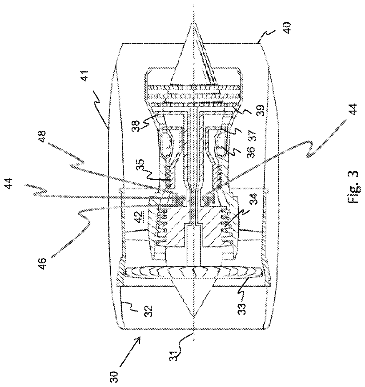
[0060]With reference to FIG. 3, a gas turbine engine is generally indicated at 30, having a principal and rotational axis 31. The engine 30 comprises, in axial flow series, an air intake 32, a propulsive fan 33, an intermediate pressure compressor 34, a high-pressure compressor 35, combustion equipment 36, a high-pressure turbine 37, an intermediate pressure turbine 38, a low-pressure turbine 39 and an exhaust nozzle 40. A nacelle 41 generally surrounds the engine 30 and defines both the intake 32 and the exhaust nozzle 40.

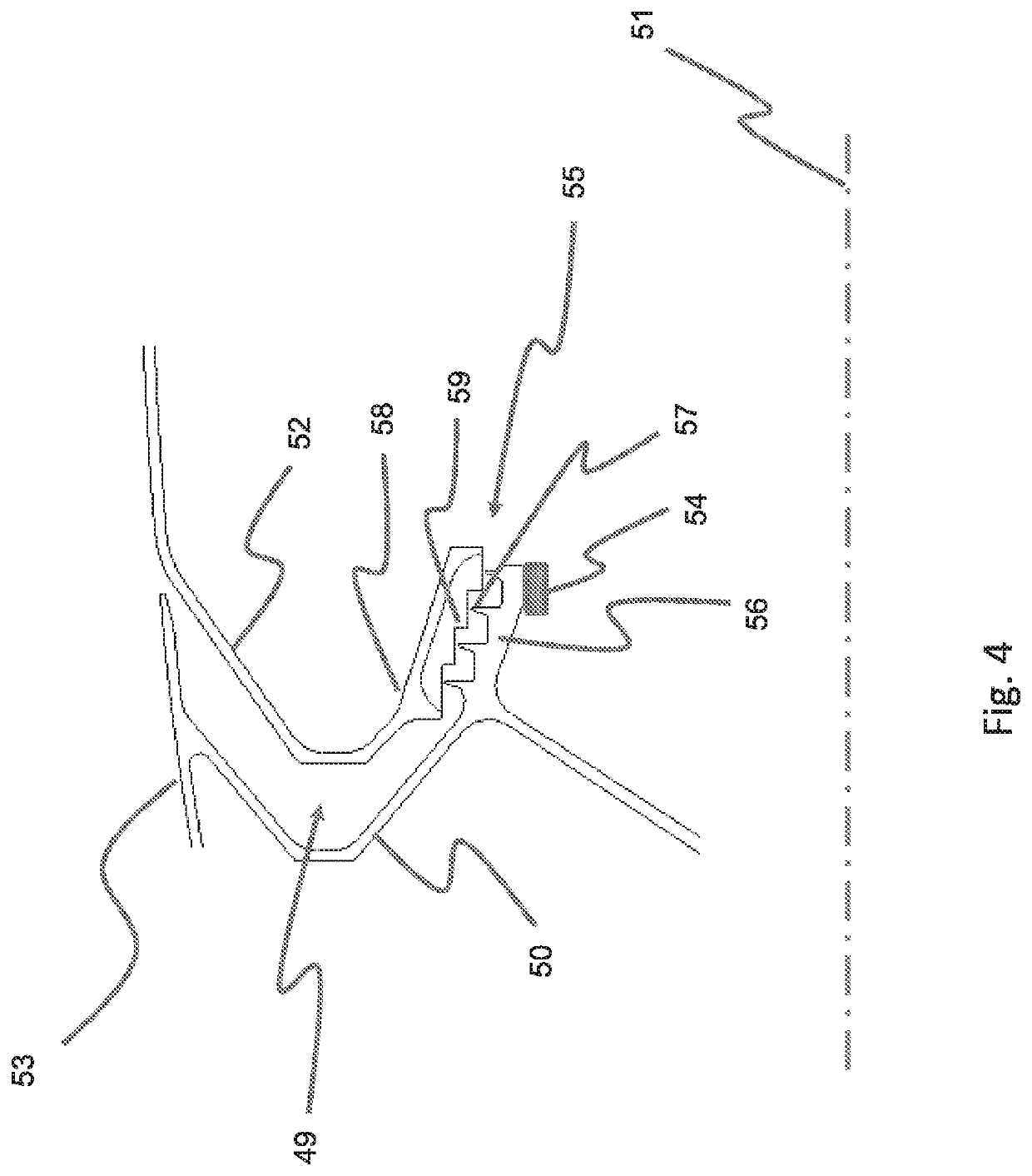
[0061]In the FIG. 3 example blades of the intermediate compressor 34 can be seen to extend radially away from a central rotor. A rotor sealing component 46 extends axially away from the intermediate compressor in the FIG. 3 example. The rotor sealing component is an annular ring. A stator sealing component 48 is positioned adjacent the rotor sealing component 46. The rotor sealing component 46 and stator sealing component 48 act to provide a seal between the rotor...


PUM


Abstract

A rotor is provided comprising a centre of mass and a rotational axis and a rotor sealing component extending circumferentially around the rotor for sealing between the rotor and a stator, wherein the centre of mass of the rotor is coincident with the rotational axis, and material of the rotor sealing component is not evenly distributed around its circumference. A stator sealing component in which the material is not evenly distributed around its circumference is also provided.

Description

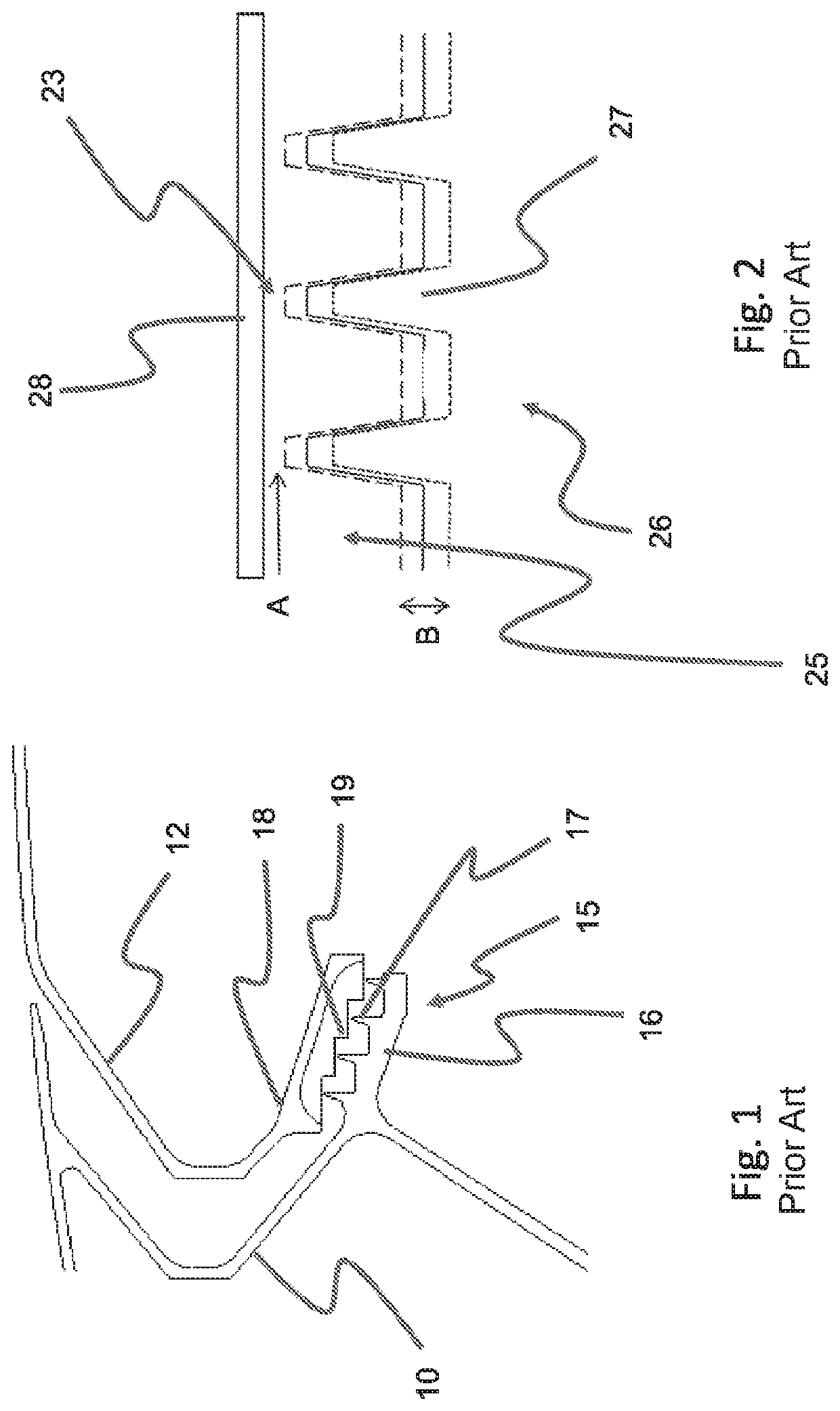
CROSS-REFERENCE TO RELATED APPLICATIONS[0001]This application is based upon and claims the benefit of priority from British Patent Application Number 1715169.7 filed 20 Sep. 2017, the entire contents of which are incorporated by reference.BACKGROUNDTechnical Field[0002]The present disclosure concerns a rotor and / or stator, a seal between a rotor and stator, gas turbine engines, and a method of de-tuning a seal between a rotor and a stator.Description of the Related Art[0003]In pressurised rotating machinery, for example a gas turbine engine, rotating parts, for example a rotor, must be sealed against static parts, for example a stator, in order to prevent fluid leakage between them. Typically a tortuous path is provided between the rotor and stator, for example a labyrinth seal, in order to minimise flow through the seal whilst also minimising frictional effects between the rotor and stator.[0004]A gas turbine engine uses seals between rotors and stators within the engine core to ma...

Claims


Application Information

Patent Timeline
Patent Type & Authority Patents(United States)
IPC IPC(8): F01D11/02F01D11/00F01D5/02F16J15/447
CPCF01D11/02F16J15/4476F01D5/027F01D11/001F05D2260/96F05D2240/55
Inventor GREEN, JEFFREY S.
Owner ROLLS ROYCE PLC
Learn More