Discharging brush, discharging device, and discharging method

a technology of discharging device and discharging method, which is applied in the direction of connection of connection contact member material, transportation and packaging, and connection device connection, etc., can solve the problems of esd, large size and thin thickness of recent display device, and inducing panel defectiveness, etc., to achieve the effect of reducing the amount of electrification

Active Publication Date: 2020-11-03
SAKAI DISPLAY PROD
View PDF14 Cites 0 Cited by
  • Summary
  • Abstract
  • Description
  • Claims
  • Application Information

AI Technical Summary

Benefits of technology

[0011]Accordingly, the present invention provides the discharging brush, the discharging device, and the discharging method capable of realizing appropriate removal of static electricity and reduction in electrification amount.

Problems solved by technology

Many of recent display devices are large in size and thin in thickness.
The electrification of a display panel may cause electro static discharge (ESD) when the display panel is brought into contact with a worker or an inspection device during manufacturing processes.
The occurrence of ESD induces panel defectiveness.
Since removal of static electricity by the noncontact-type discharging method may be insufficient for recent large and thin display panels, the contact-type discharging method using a conductive bar or brush is often employed.
However, when the static electricity of an object to be discharged, such as a display panel, having an electronic circuit is removed by using the contact-type method, if the electrification amount of the object to be discharged is large, bringing the conductive bar or brush into contact with the object may cause large current to flow instantaneously and may damage the electronic circuit in the object.

Method used


Image

  • Discharging brush, discharging device, and discharging method
  • Discharging brush, discharging device, and discharging method
  • Discharging brush, discharging device, and discharging method

Examples


first embodiment

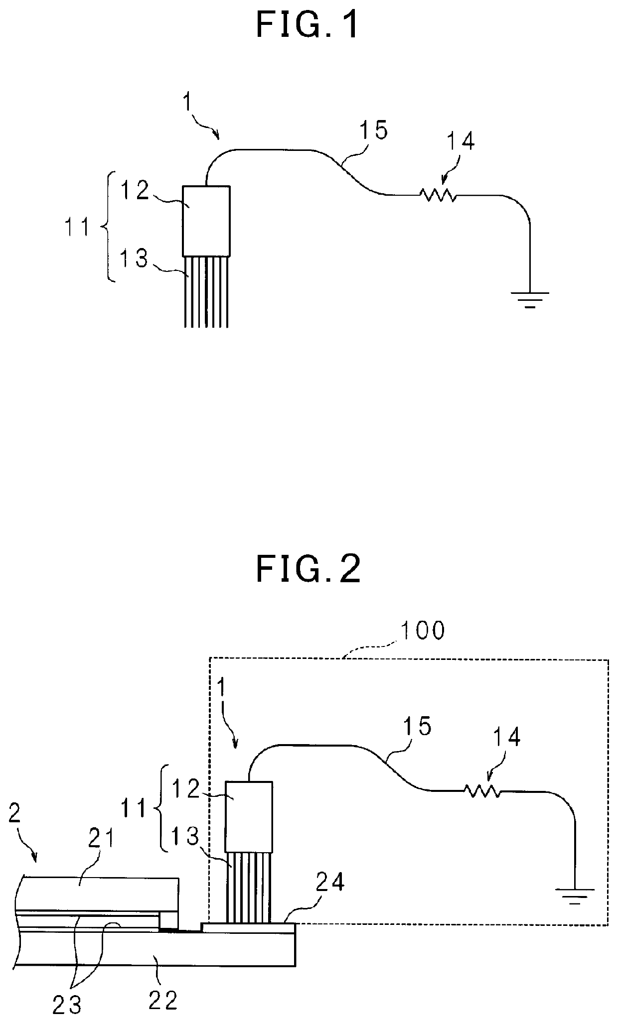
[0019]FIG. 1 schematically illustrates a discharging brush 1 according to a first embodiment. The discharging brush 1 includes a conductive brush unit 11 and a conductive wire 15. As described below, the conductive brush unit 11 is configured to contact with a terminal 24 formed on a peripheral region of the display panel to remove static electricity of the terminal 24. The conductive wire 15 is a grounding wire connecting the brush unit 11 with a grounding point via a resistor 14. The brush unit 11 includes a bristle implantation part 12 and a bristle bundle 13 implanted to a plurality of portions of the bristle implantation part 12. The bristle implantation part 12 may be, for example, made of metal and may be a flat plate having an elongated shape. The bristle bundle 13 is implanted to a lateral surface of the bristle implantation part 12 along the entire length of the bristle implantation part 12. The conductive wire 15 has a first end connected to the bristle implantation part ...

second embodiment

[0034]FIG. 6 is a block diagram illustrating an exemplary configuration of a discharging device 101 according to a second embodiment. The discharging device 101 according to the second embodiment includes a discharging brush 1b grounded via a variable resistor 142 and a control unit 16 controlling the resistance value of the variable resistor 142. Replacing the resistor 14 of the discharging brush 1 described in the first embodiment by the variable resistor 142 can obtain the discharging brush 1b according to the second embodiment. The configuration of the discharging brush 1b is similar to that of the discharging brush 1 according to the first embodiment, except for the variable resistor 142 and the control unit 16. Therefore, common constituent components are denoted by the same reference numerals and detailed description thereof will be omitted.

[0035]In the discharging device 101 according to the second embodiment, the control unit 16 changes the resistance value of the variable ...


PUM

PropertyMeasurementUnit
resistanceaaaaaaaaaa
resistance valueaaaaaaaaaa

Abstract

The discharging brush 1 includes a conductive brush unit 11 and a grounding wire 15 connecting the brush unit 11 with a grounding point via a resistor 14. In a discharging device 100, the discharging brush 1 is installed at a conveyance path for conveying a display panel 2, in such a manner that the brush unit 11 is in sliding contact with a terminal 24 formed on a peripheral region of the display panel 2 conveyed along the conveyance path. For example, the resistor 14 has a resistance value equal to or greater than 1 MΩ and equal to or less than 10 MΩ.

Description

CROSS-REFERENCE TO RELATED APPLICATION[0001]This is a continuation-in-part of PCT international application No. PCT / JP2015 / 086074 filed on Dec. 24, 2015, incorporated herein by reference.BACKGROUND OF THE INVENTION[0002]The present invention relates to a discharging brush, a discharging device, and a discharging method capable of realizing appropriate removal of static electricity and reduction in electrification amount.BACKGROUND ART[0003]Many of recent display devices are large in size and thin in thickness. Display panels of such display devices tend to be electrified in manufacturing processes. The electrification of a display panel may cause electro static discharge (ESD) when the display panel is brought into contact with a worker or an inspection device during manufacturing processes. The occurrence of ESD induces panel defectiveness. Accordingly, removal of static electricity of the display panel is necessary.[0004]As a discharging method of the panel, there is a noncontact-...

Claims


Application Information

Patent Timeline
Patent Type & Authority Patents(United States)
IPC IPC(8): H01L23/60H01R13/648H01L21/67H01L21/677H01R4/58H05F3/02H01R39/24
CPCH01R13/6485H01L21/67011H05F3/02H01L21/677H01L23/60H01R4/58H01R39/24
Inventor SUGIMOTO, SHINICHI
Owner SAKAI DISPLAY PROD
Why Eureka
Try Eureka