

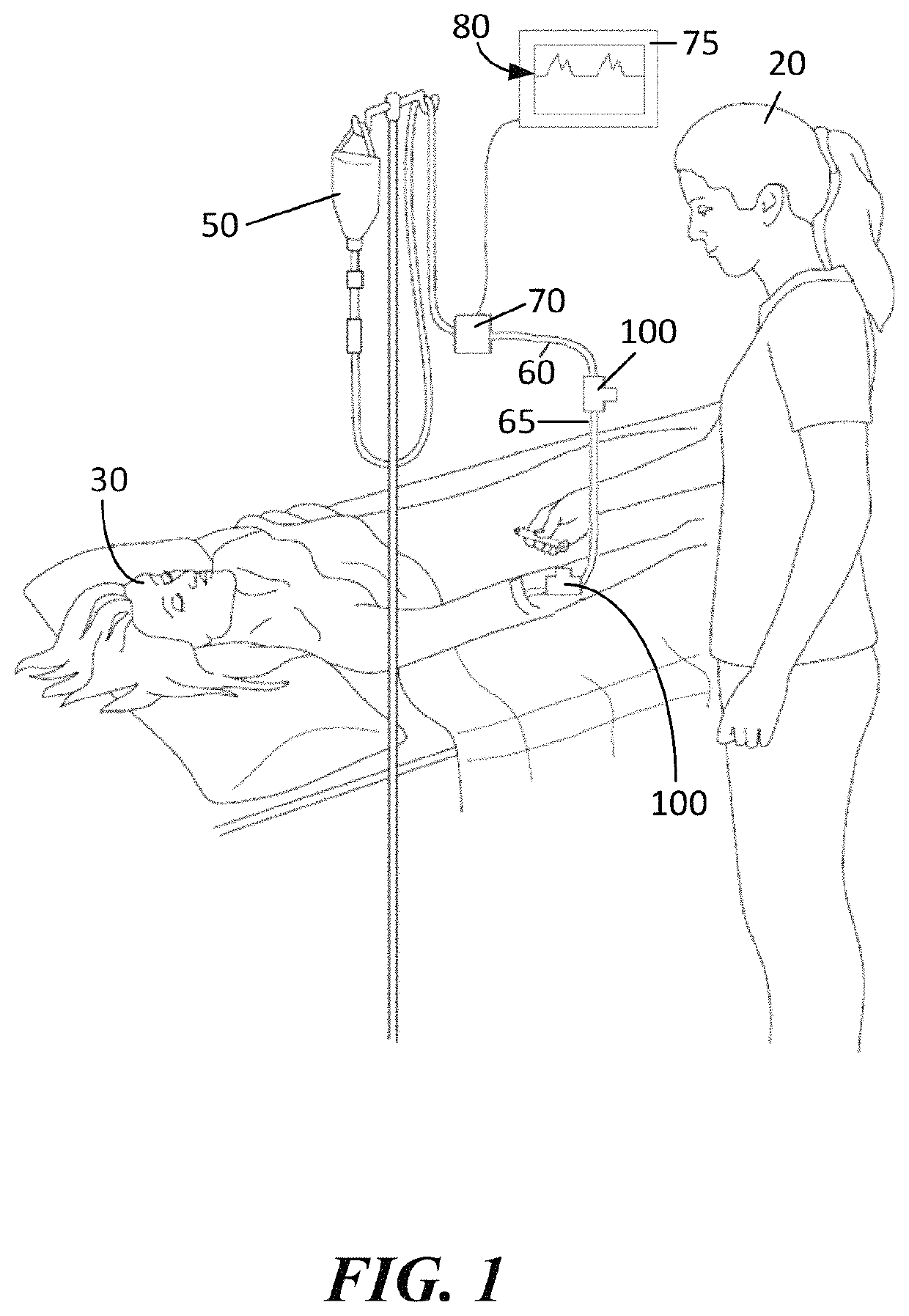
Sampling port for hemodynamic monitoring systems
a hemodynamic monitoring and sampling port technology, applied in the field of fluid delivery and medical porting devices, can solve problems such as erroneous blood pressure readings, and achieve the effect of increasing the stiffness of the wall
- Summary
- Abstract
- Description
- Claims
- Application Information
AI Technical Summary
Benefits of technology
Problems solved by technology
Method used
Image

Examples
Embodiment Construction
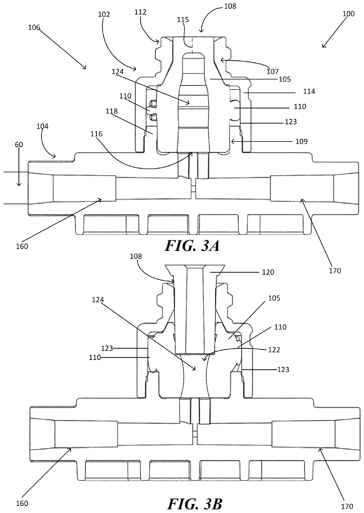
[0005]In accordance with one embodiment of the invention, a medical valve has an open mode that permits fluid flow, and a closed mode that prevents fluid flow. The valve is configured to be used in-line and in fluid communication with a pressure transducer. Accordingly the valve has a housing with an inlet and an outlet. The housing has an interior contact surface at and / or between the inlet and / or the outlet. A resilient valve element sits within the housing interior and is configured to control fluid flow through the inlet. The resilient valve element has a body including a proximal portion that forms a normally closed aperture configured to open when actuated by a medical device. The resilient valve element also has a distal portion adjacent to the outlet, and a central portion between the proximal portion and the distal portion. The central portion of the resilient valve element has a wall with an interior surface that defines a fluid chamber in the open mode and in the closed m...
PUM
 Abstract
Description
Claims
Application Information