Coherence artifacts suppression in integrated photonic systems

a photonic system and coherence artifact technology, applied in the field of photonic systems, can solve the problems of reducing the contrast of the captured or projected image, and reducing the quality of the projected or received optical signal

Active Publication Date: 2020-11-17
CALIFORNIA INST OF TECH
View PDF1 Cites 3 Cited by
  • Summary
  • Abstract
  • Description
  • Claims
  • Application Information

AI Technical Summary

Problems solved by technology

Despite these advantages, the coherence of the source results in artifacts that need to be mitigated for proper system operation.
In an optical system incorporating a coherent source, two such artifacts are edge ringing and speckle patterns that distort the quality of the projected or received optical signal.
Such artifacts reduce the contrast of the captured or projected image.
Speckle patterns, which arise from surface roughness of the imaging target, reduce the signal-to-noise (SNR) and result in destructive interference of the light at the receiver aperture.
Consequently, the reconstructed image contains dark black spots that can distort the received light to the point that in many cases it may not be possible to reconstruct the target image.

Method used


Image

  • Coherence artifacts suppression in integrated photonic systems
  • Coherence artifacts suppression in integrated photonic systems
  • Coherence artifacts suppression in integrated photonic systems

Examples


Embodiment Construction

[0027]Embodiments of the present invention reduce the speckle density in a number of ways. For a fully developed speckle pattern, the speckle density is dependent on optical wavelength, polarization, illumination distance, and illumination spot size, as defined below:

[0028]nv=KAc(1)

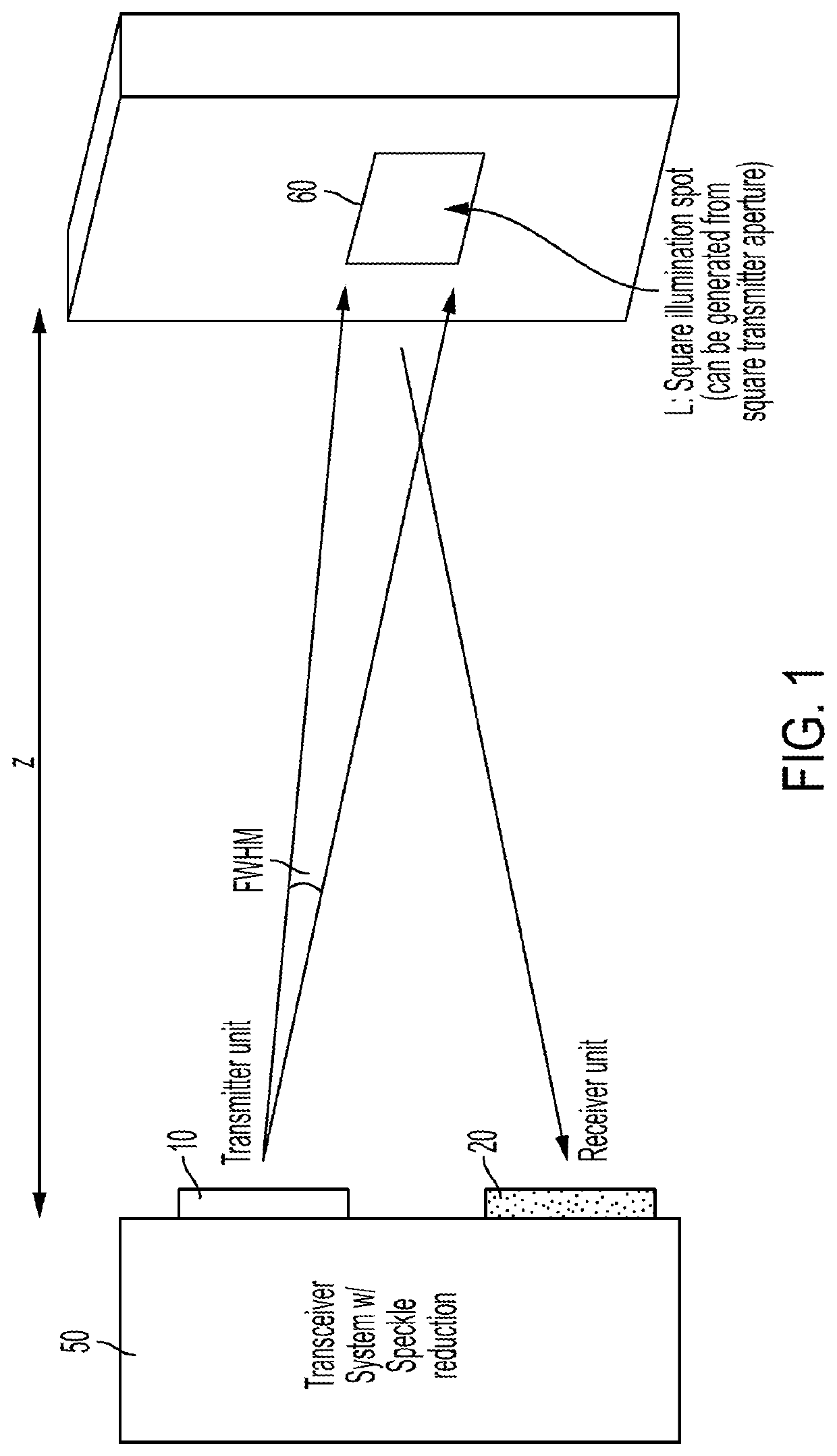
[0029]In expression (1), nν represents the density of speckle vortices, K is a constant that is geometry dependent, and Ac is defined below. FIG. 1 shows an optical transceiver 50 forming an image of target 60, in accordance with one embodiment of the present invention. Transceiver 50, shown as including, in part, a transmitter unit 10 and a receiver unit 20, is spaced away from target 60 by distance z. For a square aperture the following expressions apply:

[0030]Ac=(λ2⁢z2L2)(2)bσ2=(π23⁢Ac)(3)nv=b / σ22⁢π(4)

[0031]In expression (2), z represents the distance between the transceiver and the target, L2 represents the area of the target (see, for example, “Speckle Phenomena in Optics” by Joseph Goodman, 2006) As...


PUM

PropertyMeasurementUnit
optical phasedaaaaaaaaaa
timeaaaaaaaaaa
non-overlapping time intervalsaaaaaaaaaa

Abstract

An optical phased array includes, in part, a multitude of receiving elements arranged along N rows and M columns, and a controller configured to activate a first subset of the receiving elements during a first time interval to capture first data representative of a first image of a target, to activate a second subset of the receiving elements during a second time interval to capture second data representative of a second image of the target, and to combine the first and second data to generate the image of the target. The first and second subsets may share common receiving elements. The controller may be further configured to compute an average of the first and second data to generate the image of the target. The first subset may represent a subset of the M columns.

Description

CROSS REFERENCE TO RELATED APPLICATIONS[0001]The present application claims benefit under 35 USC 119(e) of U.S. Application Ser. No. 62 / 629,409 filed Feb. 12, 2018, the content of which is incorporated herein by reference in its entirety.FIELD OF THE INVENTION[0002]The present invention is related to photonics systems, and more particularly to reducing the coherent artifacts in such systems.BACKGROUND OF THE INVENTION[0003]Optical systems benefit from the relatively high degree of temporal and spatial coherence that a coherent optical source can provide. For example, in an imaging system, the coherence of the source can be used to reconstruct not only the intensity of the target but also the time of flight, which can be used to determine the range of the target. Furthermore, variations in the phase of a coherent source can be used in material composition detection and spectroscopic applications. In addition, a coherent source makes it possible to form a lens-free projector or imager...

Claims


Application Information

Patent Timeline
Patent Type & Authority Patents(United States)
IPC IPC(8): G02B27/00G02B27/48G02F1/29G02B27/28
CPCG02B27/0087G02F1/292G02B27/286G02B27/48G01S17/89G01S7/4863G01S7/4876G01S7/4914G01S7/493
Inventor KHACHATURIAN, AROUTINFATEMI, SEYED MOHAMMADREZAHAJIMIRI, SEYED ALI
Owner CALIFORNIA INST OF TECH
Why Eureka
Try Eureka