Link and wire harness

a technology of link and wire harness, which is applied in the direction of electrical/fluid circuit, vehicle components, electrical apparatus, etc., can solve the problems of lowering the manufacturing cost of the protector, the inability to maintain the engagement between the link and the corrugated tube, and the manufacturing cost of the wire harness

Active Publication Date: 2020-11-17
YAZAKI CORP
View PDF14 Cites 1 Cited by
  • Summary
  • Abstract
  • Description
  • Claims
  • Application Information

AI Technical Summary

Benefits of technology

[0022]According to first aspect of the invention, relating to the item [1], the link is engaged with the corrugated tube by the engagement portion. If, for example, the corrugated tube and the projection piece which projects alongside the corrugated tube are wound with a fixing tape together, the link and corrugated tube can be connected to each other more strongly than in a case the link and the corrugated tube are engaged with each other by only the engagement portion. As a result, even where too strong an external force acts on the corrugated tube, a state that the link and the corrugated tube are engaged with each other can be maintained more properly. The projection piece and the corrugated tube may be fixed to each other by a mechanical method using a clip or the like or with an adhesive or the like. The method for fixing the projection piece and the corrugated tube is not limited to winding a fixing tape on them together. The projection piece and the corrugated tube may be fixed to each other by a mechanical method using a clip or the like or with an adhesive or the like.
[0023]As such, the link having this configuration can link the corrugated tube and the protector more properly than conventional links.
[0024]Incidentally, it is possible to use the link in such a manner as to prepare, in advance, plural kinds of links that are different from each other in dimensions or shape of the internal space and selects a proper link according to the shapes etc. of the corrugated tube and the protector. Using the link in this manner makes it possible to absorb thickness differences between the corrugated tubes in fixing various corrugated tubes that are different from each other in thickness. Thus, the use of the link having this configuration makes it unnecessary to prepare protectors for corrugated tubes that are different from each other in thickness and to thereby lower the manufacturing cost of the protector (and hence the manufacturing cost of a wire harness).
[0027]According to fourth aspect of the invention, relating to the item [4], the link is engaged with the corrugated tube by the engagement portion. If, for example, the corrugated tube and the projection piece which projects alongside the corrugated tube are wound with a fixing tape together, the link and corrugated tube can be connected to each other more strongly than in a case the link and the corrugated tube are engaged with each other by only the engagement portion. As a result, even where too strong an external force acts on the corrugated tube, a state that the link and the corrugated tube are engaged with each other can be maintained more properly. Thus, the wire harness having this configuration can maintain a state that the corrugated tube and the protector are connected to each other properly.
[0028]According to fifth aspect of the invention, relating to the item [5], the corrugated tube and the projection piece of the link are wound with a fixing tape together. As a result, the link and corrugated tube can be connected to each other more strongly than in a case the link and the corrugated tube are engaged with each other by only the engagement portion. As a result, even where too strong an external force acts on the corrugated tube during use of the wire harness, a state that the link and the corrugated tube are engaged with each other can be maintained more properly.
[0029]The invention can provide a link capable of linking a corrugated tube and a protector properly as well as a wire harness that is equipped with a corrugated tube and a protector that are linked to each other by such a link.

Problems solved by technology

However, when, for example, the corrugated tube receives too strong an external force, there may occur an event that the engagement between the link and the corrugated tube cannot be maintained properly due to, for example, reduction of the diameter of the corrugated tube.
Thus, the use of the link having this configuration makes it unnecessary to prepare protectors for corrugated tubes that are different from each other in thickness and to thereby lower the manufacturing cost of the protector (and hence the manufacturing cost of a wire harness).

Method used


Image

  • Link and wire harness
  • Link and wire harness
  • Link and wire harness

Examples


embodiment

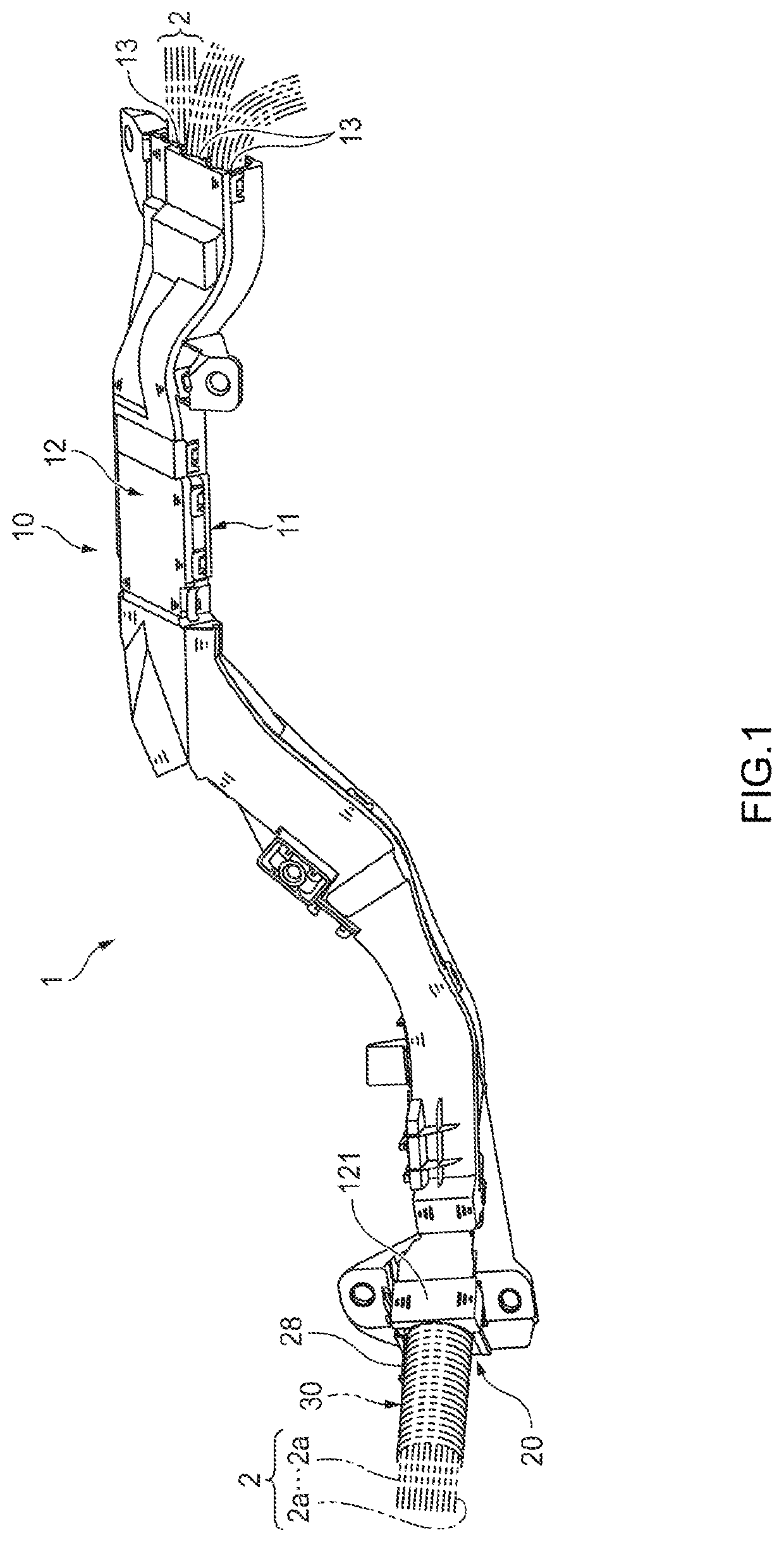
[0038]A link 20 and a wire harness 1 according to an embodiment of the present invention will be hereinafter described with reference to the drawings.

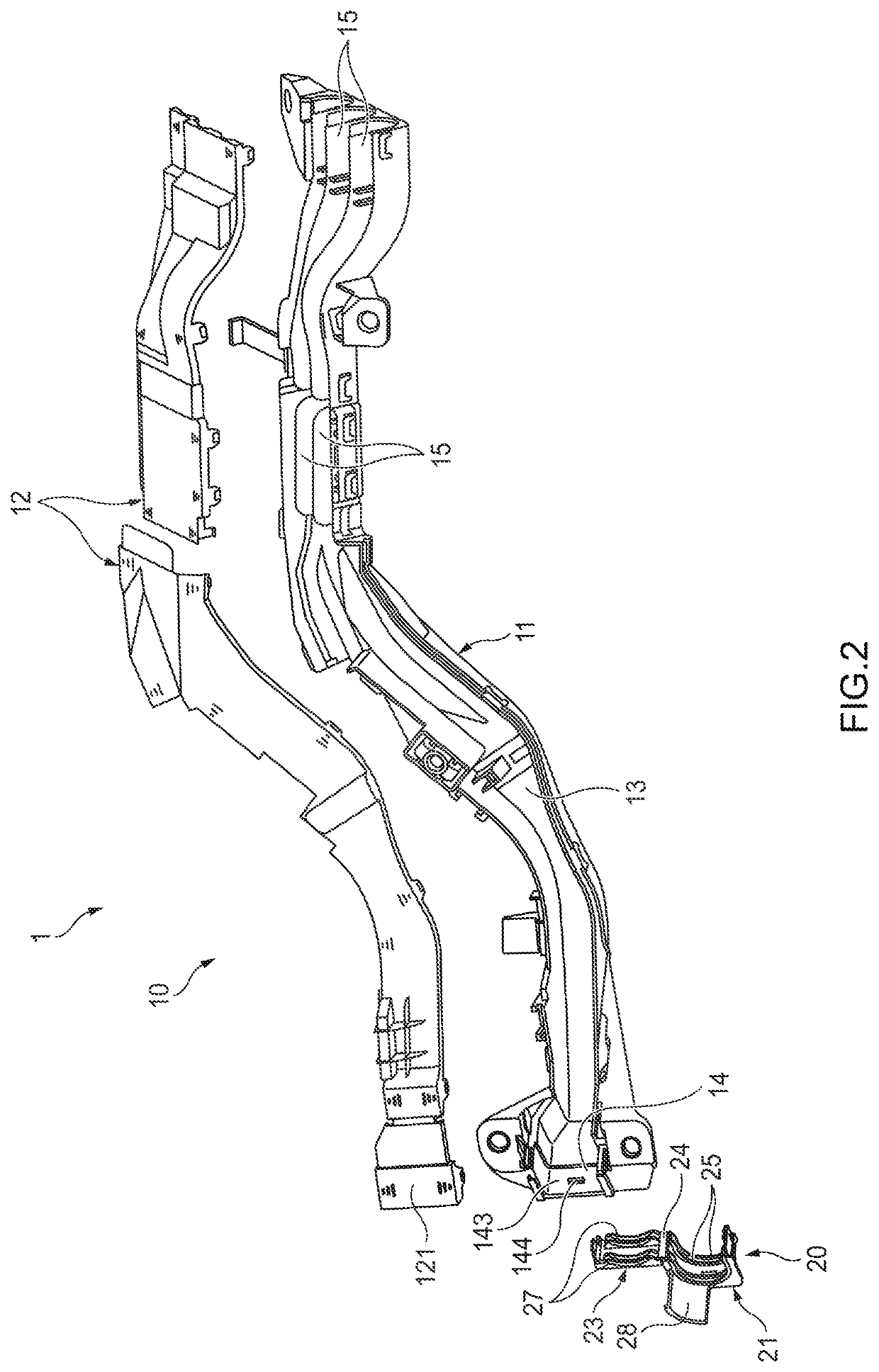
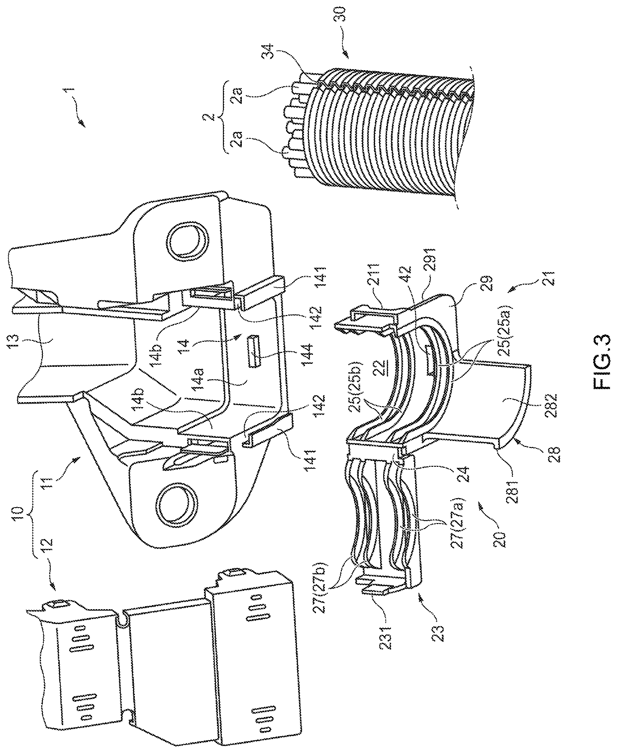
[0039]As shown in FIG. 1, the wire harness 1 according to the embodiment is equipped with a protector 10 which houses an electric wire bundle 2 consisting of plural electric wires 2a and a link 20 which is provided at an end portion of the protector 10. The link 20 is also called a protector stopper. The protector 10 is a member for routing the electric wire bundle 2 along a prescribed route in its internal space and fixing the electric wire bundle 2 to an attachment target body such as a vehicle body. The link 20 is a member for fixing, to the end portion of the protector 10, a corrugated tube 30 which houses the electric wire bundle 2 and can be bent into an arbitrary shape.

[0040]As shown in FIGS. 1 and 2, the protector 10 is equipped with a protector main body 11 in which an approximately C-shaped sectional shape continues in its lo...


PUM


Abstract

A link connects a corrugated tube to a box-shaped protector. The link includes an engagement portion capable of engaging with the corrugated tube, an attachment portion capable of attaching to the protector, and a projection piece projecting alongside the corrugated tube.

Description

CROSS-REFERENCES TO RELATED APPLICATION(S)[0001]This application is based on and claims priority from Japanese Patent Application No. 2018-206077 filed on Oct. 31, 2018, and the entire contents of which are incorporated herein by reference.BACKGROUNDField of the Invention[0002]The present invention relates to a link for linking a corrugated tube and a box-shaped protector to each other and to a wire harness.Description of Related Art[0003]Conventionally, among methods for routing an electric wire bundle in, for example, an automobile body is a method in which the electric wire bundle is housed in a corrugated tube and the corrugated tube is fixed to a box-shaped protector. In general, corrugated tubes have large-diameter portions and small-diameter portions that are arranged alternately along the axial line. In fixing such a corrugated tube to a protector, a link for linking the corrugated tube to the protector may be used.[0004]For example, one conventional link has a tubular shape...

Claims


Application Information

Patent Timeline
Patent Type & Authority Patents(United States)
IPC IPC(8): H02G3/06H02G3/04B60R16/02
CPCH02G3/06B60R16/0207H02G3/0468H02G3/0625H02G3/0691H02G3/0487B60R16/0215
Inventor YAMAUCHI, AKINORIKATO, TORU
Owner YAZAKI CORP
Why Eureka
Try Eureka