
Electric vehicle

a technology of electric vehicles and electric motors, applied in the direction of safety/protection circuits, electric devices, capacitor propulsion, etc., can solve the problems of dc-link condensers and loads that dc-link condensers and loads may electrically break, and the condenser and load may not be charged, so as to prevent load, improve the accuracy of initial charging control, and improve the effect of initial charging control

Active Publication Date: 2020-11-24
HANWHA AEROSPACE CO LTD
View PDF39 Cites 1 Cited by
  • Summary
  • Abstract
  • Description
  • Claims
  • Application Information

AI Technical Summary

Benefits of technology

The present electric vehicle has a software type and hardware type condenser charging circuit that can be used adaptively. This has the following benefits: 1. If there is an error in the software or controller, the hardware type condenser charging circuit can be used instead, ensuring normal charging of the DC-link condenser and preventing problems such as not operating the electric vehicle or electric damages. 2. The hardware type condenser charging circuit is used when the controller controls it or when the user directly switches it, improving the accuracy of initial charging control. 3. If the hardware type condenser charging circuit is partially broken, a part of the software type condenser charging circuit can be used instead, improving the accuracy of initial charging control and ensuring continued operation of the electric vehicle.

Problems solved by technology

In this case, the DC-link condenser and the loads may electrically break.
First, when there is an error in the software or in operations of the controller during the initial charging stage, the DC-link condenser may not be charged.
Second, if there is an error in the software or in operations of the control during the initial charging stage, the DC-link condenser and loads may electrically break.
In particular, if the above problems occur in the electric vehicle in a state of manned driving, not unmanned driving, passengers in the electric vehicle may be severely damaged.
For example, if a soldier is in a battle while driving a military use electric vehicle, the soldier may be endangered.
Third, since the controller indirectly controls the DC-link condenser while monitoring the voltage between the opposite ends of the DC-link condenser at the initial stage of charging, accuracy of initial charging control is not excellent.

Method used


Image

  • Electric vehicle
  • Electric vehicle
  • Electric vehicle

Examples


Embodiment Construction

Technical Problem

[0014]One or more embodiments of the present disclosure relate to an electric vehicle capable of addressing problems in an initial charging operation via software according to the related art.

Technical Solution

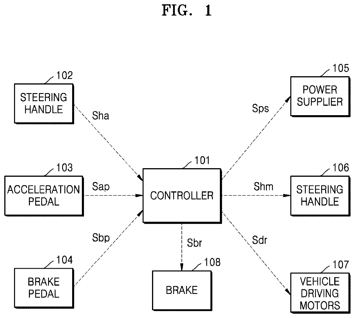
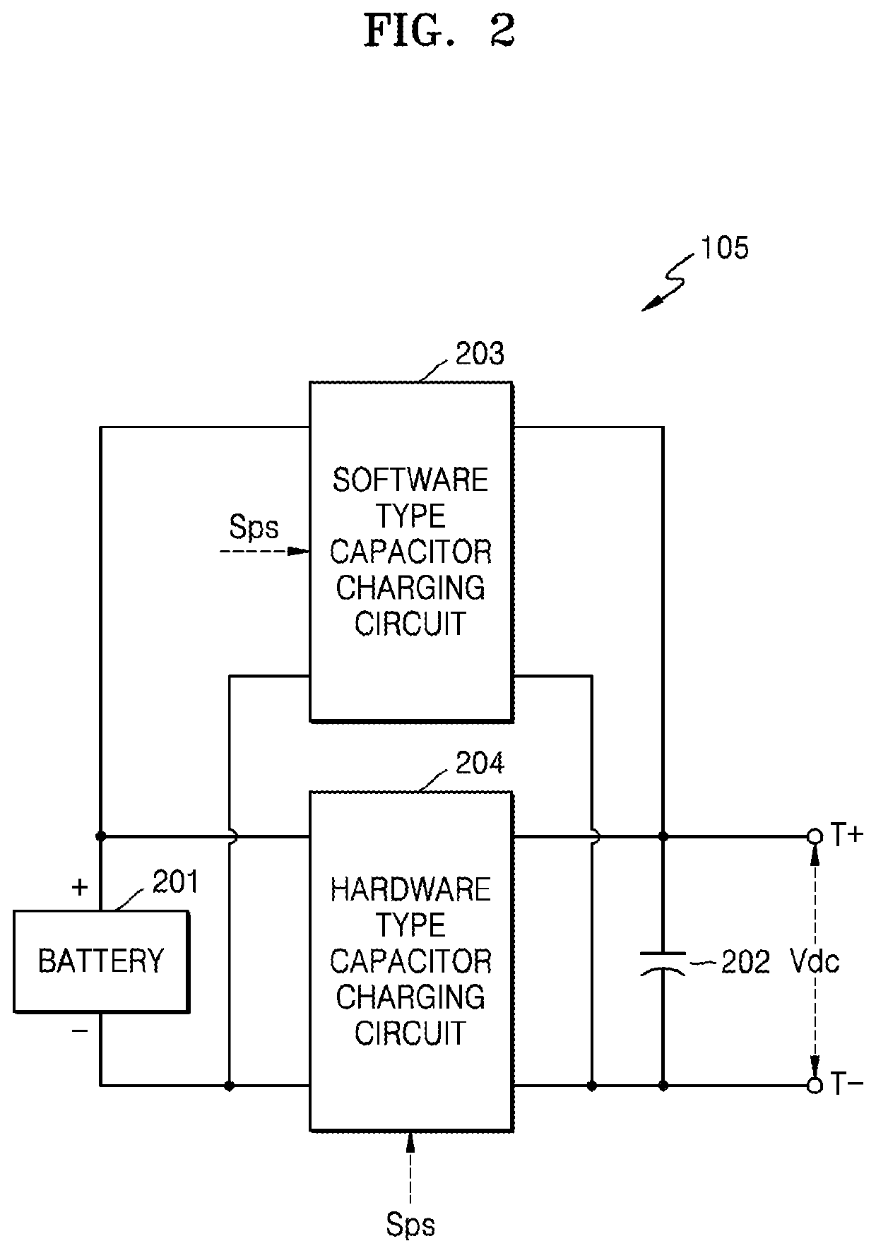
[0015]According to an embodiment of the present invention, there is provided an electric vehicle driven by at least one vehicle driving motor, the electric vehicle including: a controller and an electric power supplier, wherein the electric power supplier includes: a direct-current (DC) power source; a DC-link condenser; a software type condenser charging circuit; and a hardware type condenser charging circuit.

[0016]Electrical loads are connected to the DC-link condenser.

[0017]The software type condenser charging circuit is connected between the DC power source and the DC-link condenser, and is configured to operate when the controller controls the software type condenser charging circuit while monitoring a voltage between opposite ends of the DC-link condense...


PUM


Abstract

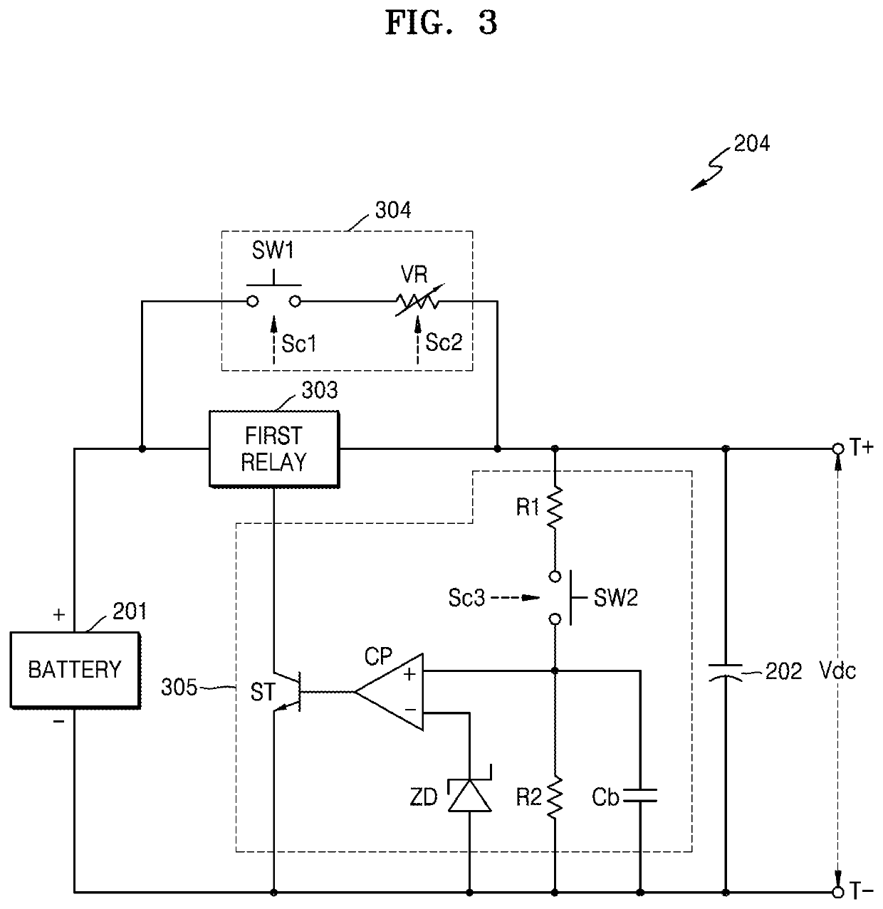
In an electric vehicle, a power supplier includes a software type condenser charging circuit and a hardware type condenser charging circuit. The software capacitor charging circuit operates when a controller controls the software type condenser charging circuit while monitoring a voltage between opposite ends at an initial charging stage. The hardware type condenser charging circuit is operated when the controller controls the hardware type condenser charging circuit without monitoring the voltage between the opposite ends of the DC-link condenser or by direct switching manipulation of a user.

Description

TECHNICAL FIELD[0001]The present invention relates to an electric vehicle, and more particularly, to an electric vehicle driven by at least one vehicle driving motor.BACKGROUND ART[0002]In general, electric vehicles including hybrid electric vehicles (hereinafter, referred to as electric vehicles) are driven by at least one vehicle driving motor.[0003]For example, when six in-wheel motors are used, six vehicle driving motors and six motor drivers are necessary. In addition, when one traction motor is used, one vehicle driving motor and one motor driver are necessary.[0004]In the above electric vehicles, electrical loads including the motor driver receive electric power via a direct current (DC)-link condenser. That is, when an electric switch of an electric vehicle is turned on by manipulation of a user, the DC-link condenser is charged by a battery that is a DC power source and then the electric power is supplied to each of components.[0005]Right after the turning-on of the electri...

Claims


Application Information

Patent Timeline
Patent Type & Authority Patents(United States)
IPC IPC(8): B60L3/00H02J7/34H02J7/00B60L50/40B60L15/20B60L15/22
CPCH02J7/00B60L3/0046H02J7/345B60L15/20B60L50/40B60L2240/547B60L15/2009B60L2250/24B60L15/22B60L15/2018B60L2250/12Y02T10/72H02J7/0031Y02T10/70H02J7/007B60Y2200/91B60Y2200/92
Inventor HAN, SEONG HUNCHAE, HEE SEOPARK, SUNG EUN
Owner HANWHA AEROSPACE CO LTD
Learn More