
Controlling a load commutated converter during undervoltage

a load commutation converter and load technology, applied in the field of load commutation converters, can solve the problems of weak grid, low load efficiency, and low load efficiency, and achieve the effect of reducing load power consumption and restricting the maximum torque of the machin

Active Publication Date: 2017-09-28
ABB (SCHWEIZ) AG
View PDF2 Cites 1 Cited by
  • Summary
  • Abstract
  • Description
  • Claims
  • Application Information

AI Technical Summary

Benefits of technology

The patent text describes how to handle an undervoltage condition in a grid. The text explains that the load commutated converter can continue to operate even if there is not enough voltage in the grid. However, if the current is too large, the drive may be tripped to prevent electrical damage. The technical effect of this patent is to provide a method for safely and effectively handling undervoltage conditions in a grid.

Problems solved by technology

Load commutated converters are often employed at remote places, where the grid conditions may be far from ideal.
Long cables to the power generation may result in a weak grid, i.e. the grid voltage may have a relatively high dependence on the grid current.
Weather conditions, line interruptions and the consumption pattern of other large power consumers in the vicinity of a load commutated converter may result in brownouts, in the following also referred to as undervoltage condition, grid voltage sags, voltage dips or temporary power losses.
Processes which are powered by a load commutated converter may be quite sensitive to a loss of drive torque.
A voltage dip may lead to tripping all compressors of a plant which is especially bad as the process needs to be stopped completely and then restarted.

Method used


Image

  • Controlling a load commutated converter during undervoltage
  • Controlling a load commutated converter during undervoltage
  • Controlling a load commutated converter during undervoltage

Examples


Embodiment Construction

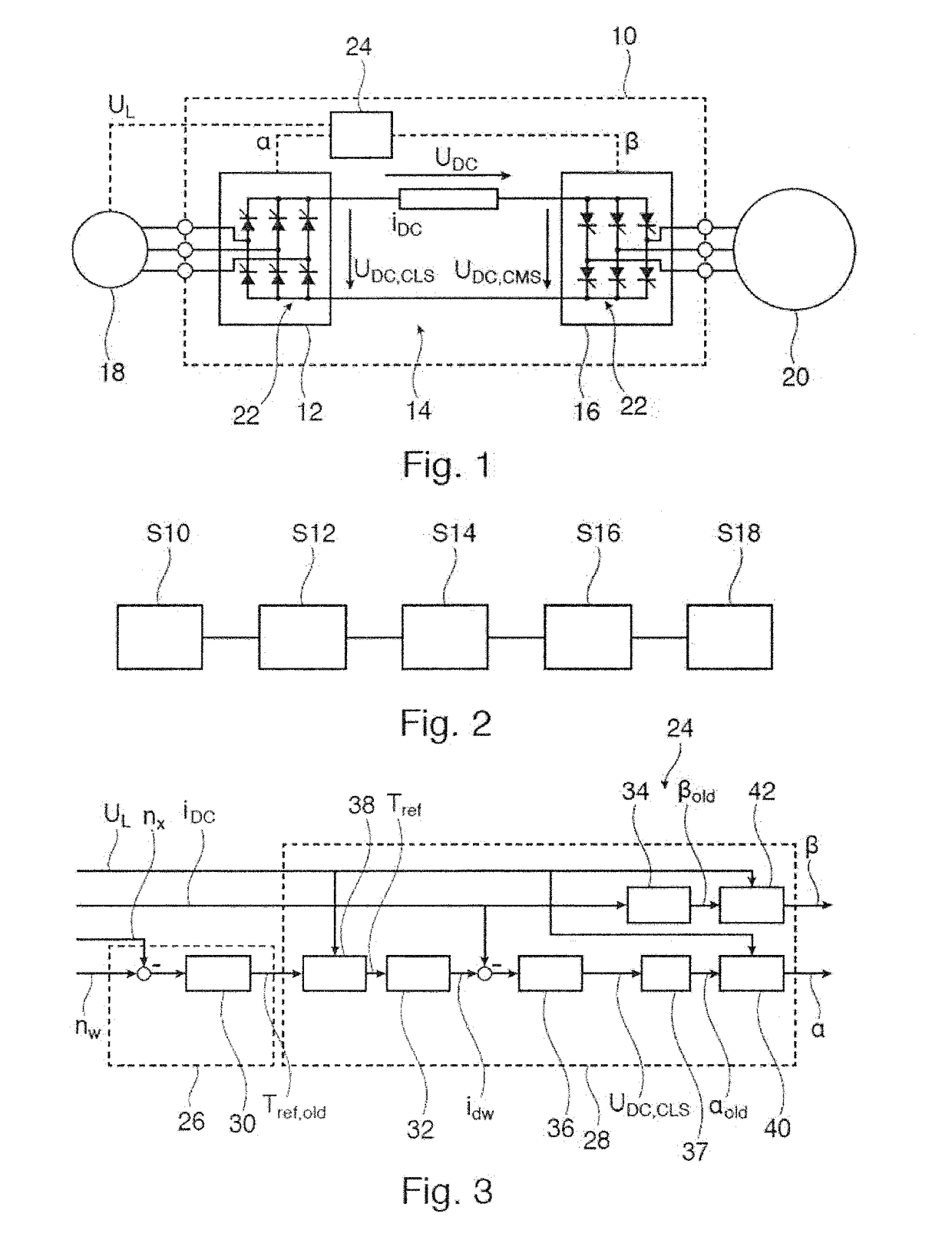
[0010]In general, in one approach of dealing with undervoltage condition in the grid, the normal operation of the load commutated converter may be continued in the case of an undervoltage condition. If the AC or DC currents are too large at the return of the nominal grid voltage, the drive may be tripped to prevent electrical damage.

[0011]With this approach, only small deviations from the nominal grid voltage may be accommodated. Larger deviations usually result in a depletion of the DC link inductance, because the machine-side converter drains more energy than can be provided by the line-side converter under the prevalent grid conditions. Overcurrent trips at the return of the grid voltage are also possible.

[0012]According to a second approach, if the grid voltage magnitude falls under a certain threshold (for example 80% of a nominal grid voltage), a trip may be activated stopping the operation of the converter. Such a threshold may be combined with a time condition, i.e. the grid...


PUM


Abstract

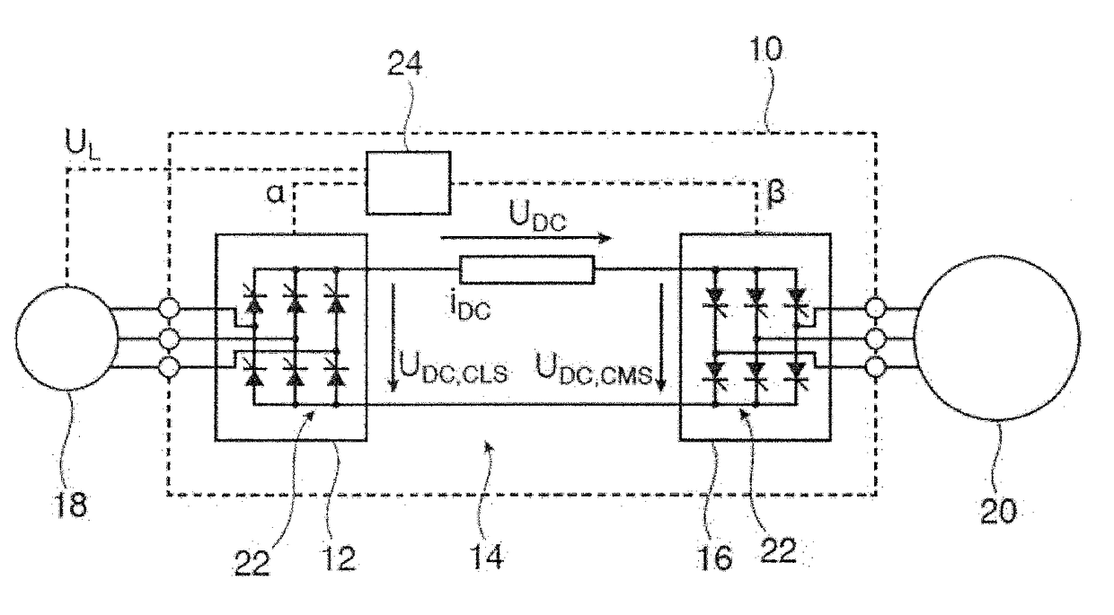
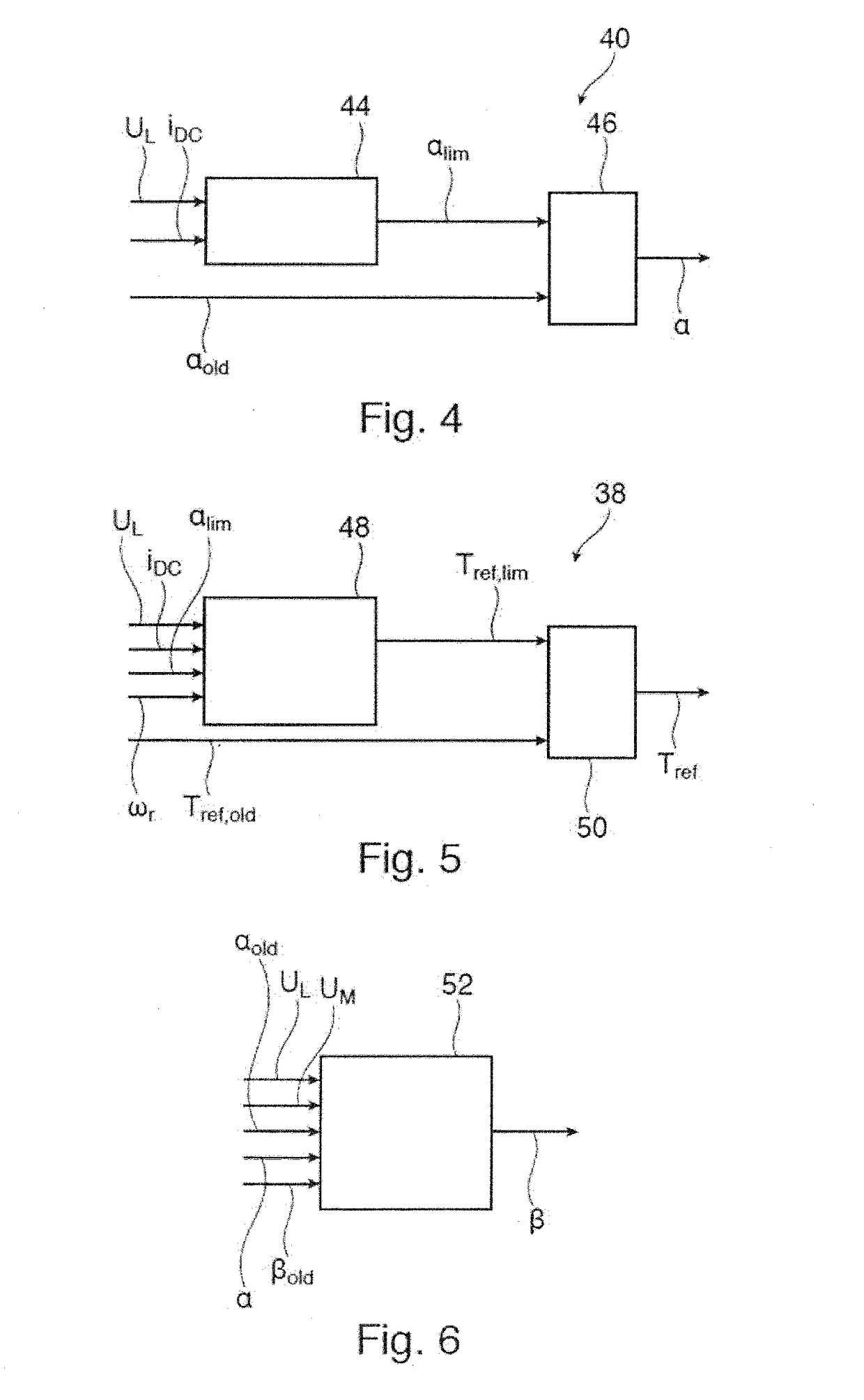
A load commutated converter interconnects an AC power grid with an AC load and comprises a grid-side converter, a DC link and a load-side converter. A method for controlling the load commutated converter comprises: determining a gridside firing angle for the grid-side converter; determining a load-side firing angle for the load-side converter; determining a grid voltage of the AC power grid; modifying the grid-side firing angle and / or the load-side firing angle based on the grid voltage, such that when an undervoltage condition in the AC power grid occurs, the operation of the load commutated converter is adapted to a change in the grid voltage; and applying the grid-side firing angle to the grid-side converter and the load-side firing angle to the load-side converter.

Description

FIELD OF THE INVENTION[0001]The invention relates to a method, a computer program, a computer-readable medium and a controller for controlling a load commutated converter. Furthermore, the invention relates to a load commutated converter.BACKGROUND OF THE INVENTION[0002]Medium voltage converters are typically employed to transform AC power of fixed frequency into AC power of varying frequency, or vice versa. The AC power of fixed frequency is provided by an electric grid, while the AC power of varying frequency is used to supply loads, such as electrical AC machines such as asynchronous machines, synchronous machines or doubly-fed machines.[0003]In most configurations, the frequency transformation is carried out in a two-step approach: First, the AC power of fixed frequency is rectified to DC power and subsequently the DC power is inverted into AC power of the desired frequency. In the power generation mode, the power flow is reversed and the varying-frequency AC power of the load i...

Claims


Application Information

Patent Timeline
Patent Type & Authority Applications(United States)
IPC IPC(8): H02M5/451G05B15/02H02M1/00
CPCH02M5/451H02M2001/0003G05B15/02H02M1/00H02M5/4505H02M1/325H02H7/1216H02M1/0003
Inventor BESSELMANN, THOMASALMER, STEFANWIIK, JANVAN DE MOORTEL, STURE
Owner ABB (SCHWEIZ) AG
Learn More