
Robotic system and method for manufacturing of objects

a robot and manufacturing technology, applied in the field of robot system and method for manufacturing objects, can solve the problems of simple single-ruled surface, simple straight lines of hot wire frames, etc., and achieve the effect of minimizing difference or distance and minimizing elastic energy

Active Publication Date: 2020-12-08
DANMARKS TEKNISKE UNIV
View PDF29 Cites 0 Cited by
  • Summary
  • Abstract
  • Description
  • Claims
  • Application Information

AI Technical Summary

Benefits of technology

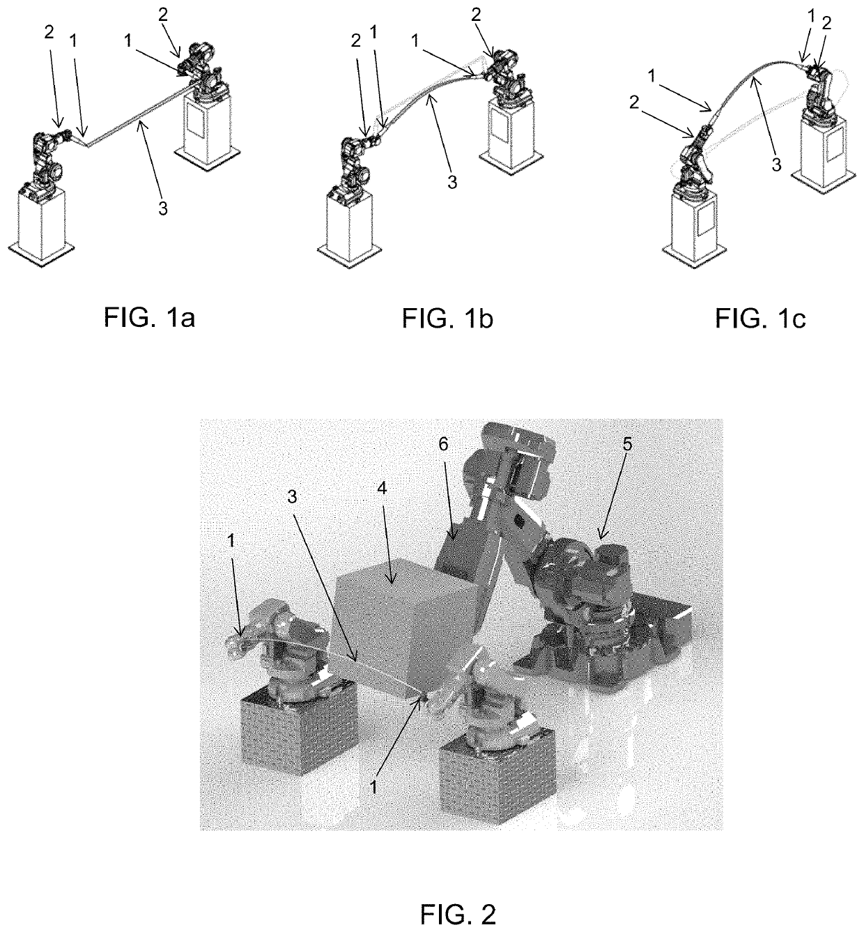
[0011]The method allows for more efficient manufacturing of molds having complex shapes, and thereby also more efficient manufacturing of objects having complex shapes. The disclosed technique for controlling two end effectors and a flexible cutting element is significantly faster and more efficient than manual formwork production and automated CNC milling.
[0015]For each planar curve, at least one elastic curve that represents the planar curve is calculated. An Euler elastica or elastic curve is the solution to the variational problem of minimizing the bending energy among curves of a given length with fixed endpoints and with the tangents prescribed at the endpoints. For the presently disclosed method, this means that the flexible cutting element is fixed between the two end effectors. The shape of the cutting element is the curve that, subject to the endpoint constraints, minimizes the elastic energy. Preferably, the calculated elastic curve should represent a shape as close as possible to the corresponding planar curve of the surface segment. Different approaches may be used to minimize the difference or distance between the elastic curve and the planar curve.

Problems solved by technology

However, the frame with hotwire could only cut straight lines, or simple single-ruled surfaces if the frame with hotwire would be moved in a ruled movement.

Method used


Image

  • Robotic system and method for manufacturing of objects
  • Robotic system and method for manufacturing of objects
  • Robotic system and method for manufacturing of objects

Examples


Embodiment Construction

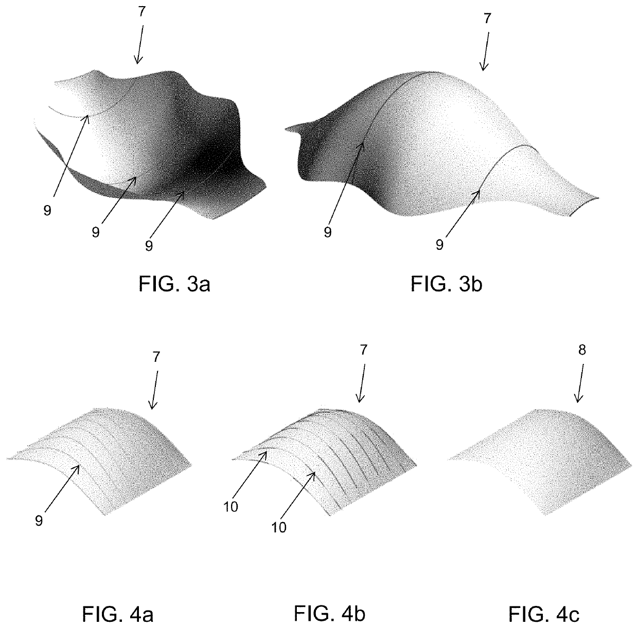
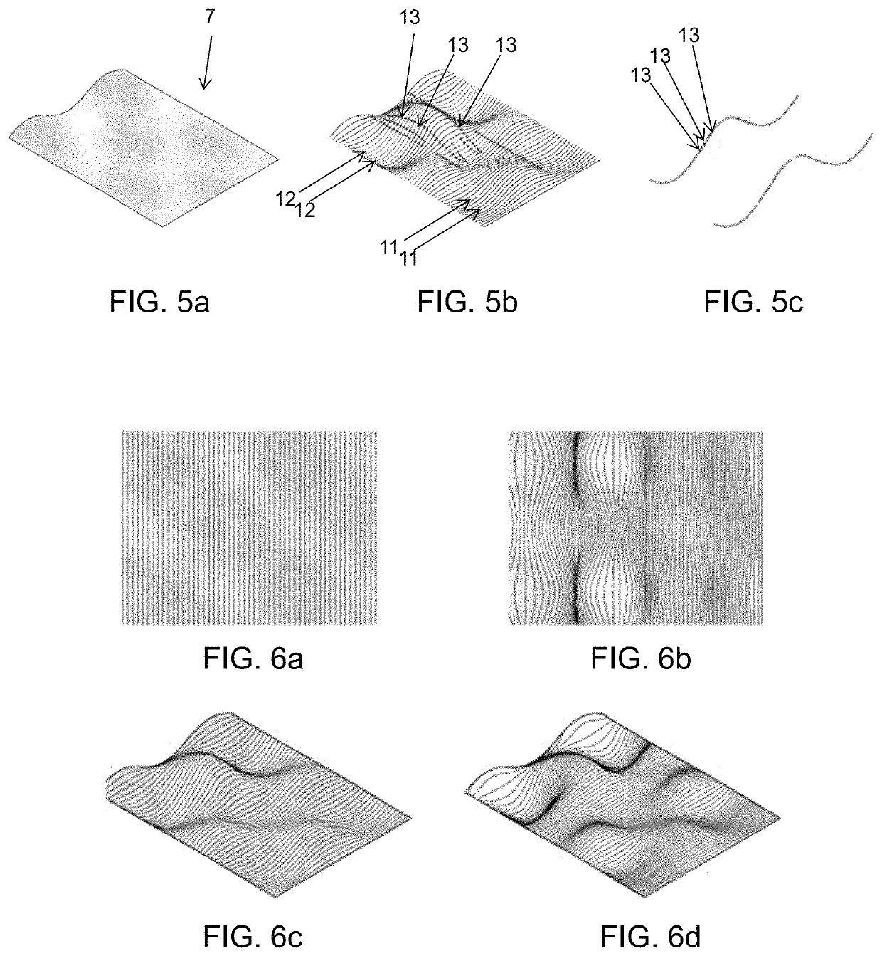
[0041]The present disclosure relates to a method for representing a surface by dividing it into segmented curves of the surface, express the curves in terms of elastic-swept surfaces, applying an approximation algorithm by extracting a number of parameters and optimizing the parameters to get a close fit to the original curves. By interpolating the control parameters a rationalized design is obtained—a new surface, which is swept out by elastic curves moving through space.

[0042]In a first embodiment, a method for manufacturing a mold for creation of complex objects, such as concrete objects, by controlling and moving two end effectors of a robotic system, the two end effectors having a flexible cutting element attached to and extending between the two end effectors, comprises the steps of:[0043]defining at least one surface representing the inner surface of the mold;[0044]dividing the surface into a number of segments represented by planar curves on the surface;[0045]for each planar...


PUM


Abstract

A method and a system for manufacturing a mold for creation of complex objects by controlling and moving two end effectors of a robotic system is provided. The two end effectors have a flexible cutting element attached to, and extending between, the two end effectors. The method includes the steps of: defining at least one surface representing the inner surface of the mold; dividing the surface into a number of segments represented by planar curves on the surface; for each planar curve, calculating at least one elastic curve representing the planar curve; for each calculated elastic curve, calculating a set of data corresponding to placement and direction of the two end effectors for configuring the flexible cutting element to a shape corresponding to the calculated elastic curve; and sequentially positioning the end effectors according to each set of data. The flexible cutting element thereby cuts the mold from a block.

Description

CROSS-REFERENCE TO RELATED APPLICATIONS[0001]This application is a Section 371 of International Application No. PCT / EP2017 / 055958, filed Mar. 14, 2017, which was published in the English language on Sep. 21, 2017, under International Publication No. WO 2017 / 157917 A1, which claims priority under 35 U.S.C. § 119(b) to European Application No. 16160088.7, filed Mar. 14, 2016, and the disclosures of which are incorporated herein by reference.BACKGROUND OF THE INVENTION[0002]The present disclosure relates to a robotic system and method for manufacturing of objects, in particular objects having complex shapes, by controlling a robot having two end effectors and a cutting element attached to and extending between the two end effectors.[0003]The vast majority of contemporary building designs are restrained to a formal language of planar surfaces and derivative geometric constructs; a constraint that stems from the practicalities of construction, which favors the use of mass-produced semi-m...

Claims


Application Information

Patent Timeline
Patent Type & Authority Patents(United States)
IPC IPC(8): B25J11/00B26D1/00B25J9/00B25J9/16B26D5/00B26F3/08B26D5/06B26D5/08B26D1/547G05B19/4099B26D7/01B26D3/00G06T17/30
CPCB25J9/1682B26D3/006B25J11/0055B26D5/06G06T17/30B26D5/086B26D5/005B26F3/08B26D1/547B26D7/01B25J9/009G05B19/4099G05B2219/40205G05B2219/39109B26D2001/006
Inventor GRAVESEN, JENSBRANDER, DAVIDBÆRENTZEN, JAKOB ANDREASMARKVORSEN, STEENBJERGE NØRBJERG, TOKEHORNBAK STEENSTRUP, KASPER
Owner DANMARKS TEKNISKE UNIV
Learn More