Rotary machine and diaphragm

a diaphragm and rotary machine technology, applied in the direction of non-positive displacement fluid engines, radial flow pumps, pump components, etc., can solve the problems of large disturbance of the flow loss of working fluid, and increase of the flow loss of the working fluid, so as to achieve the effect of minimizing the loss

Active Publication Date: 2020-12-29
MITSUBISHI HEAVY INDUSTIES COMPRESSOR CORP
View PDF22 Cites 0 Cited by
  • Summary
  • Abstract
  • Description
  • Claims
  • Application Information

AI Technical Summary

Benefits of technology

[0007]However, when the distal end portion is rounded in this manner, a step difference is formed to protrude from the curved surface. The flow of a working fluid flowing through the return bend part is disturbed due to this step difference and a loss is generated in the flow of the working fluid. Particularly, when a step difference is formed on the downstream side of the return bend part, the flow of the working fluid is largely disturbed and a flow loss of the working fluid increases. For this reason, it is desirable to minimize a loss caused by the flow of the working fluid in the return bend part while securing the strength of the diaphragms.
[0008]The present disclosure provides a rotary machine and a diaphragm capable of minimizing a loss caused by a flow of a working fluid in a return bend part while securing the strength of the diaphragm.
[0010]With such a constitution, the convex part is formed so that the surface facing the axial direction extends from the curved flow path formation surface. For this reason, the thickness in the radial direction of the distal end of the curved flow path formation surface increases by the thickness of the convex part. Since the convex part is engaged with the concave part, it is possible to prevent the distal end of the curved flow path formation surface on which the convex part is formed from protruding inward in the radial direction in the return bend part. Therefore, it is possible to prevent the working fluid flowing through the return bend part from colliding with the end portion of the diaphragm to generate a loss.
[0012]With such a constitution, the convex part is formed at the boundary between the outer flow path formation surface and the curved flow path formation surface which form a region on the downstream side of the return bend part. For this reason, it is possible to prevent the occurrence of the loss caused by a flow disturbance in a region on the downstream side of the return bend part in which the process gas is easily collected on the outer side in the radial direction. Therefore, it is possible to effectively prevent the loss caused by the flow of the process gas in the return bend part.
[0014]With such a constitution, it is possible to position a position of the diaphragm in the axial direction with respect to the outer casing by the second concave part and the second convex part which have a small dimensional tolerance in the axial direction instead of the first concave part and the first convex part. Therefore, it is possible to prevent the first convex part from being deformed due to the applied load and distorting the shape of the return bend part.
[0019]According to the present disclosure, it is possible to minimize a loss caused by a flow of a working fluid in a return bend part while securing the strength of a diaphragm.

Problems solved by technology

The flow of a working fluid flowing through the return bend part is disturbed due to this step difference and a loss is generated in the flow of the working fluid.
Particularly, when a step difference is formed on the downstream side of the return bend part, the flow of the working fluid is largely disturbed and a flow loss of the working fluid increases.

Method used


Image

  • Rotary machine and diaphragm
  • Rotary machine and diaphragm

Examples


Embodiment Construction

[0022]Embodiments for implementing a rotary machine and diaphragms according to the present disclosure will be described below with reference to the accompanying drawings. However, the present disclosure is not limited to only these embodiments.

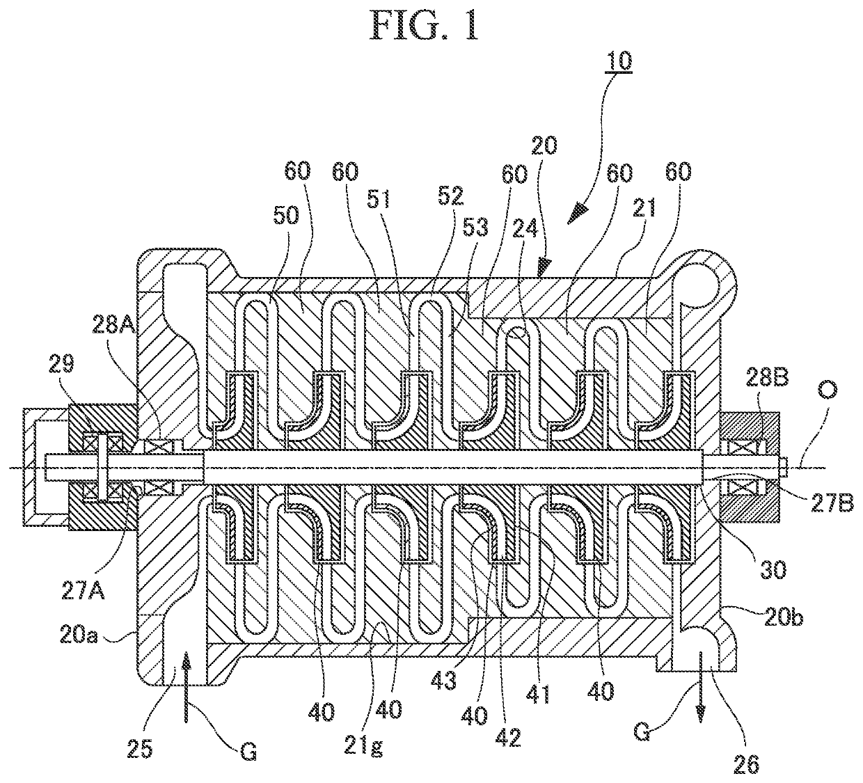
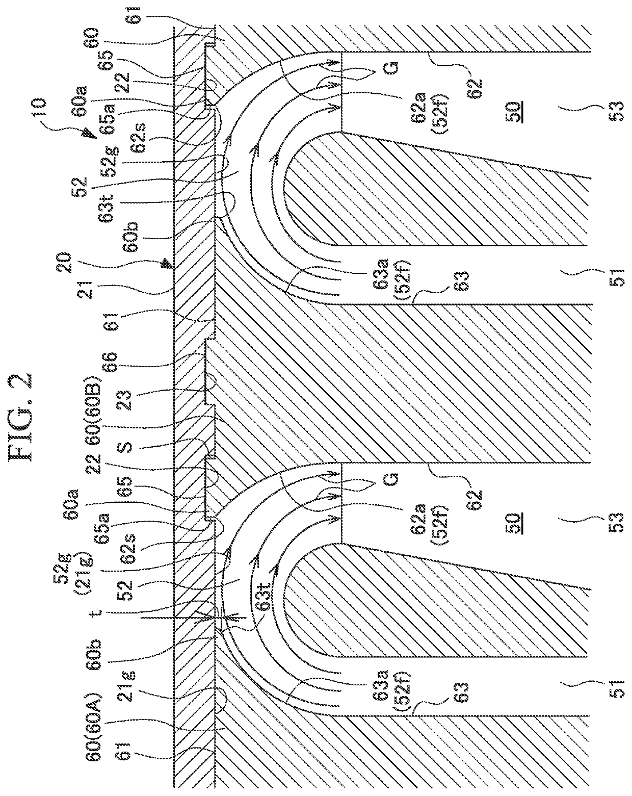
[0023]FIG. 1 is a cross-sectional view showing a constitution of a centrifugal compressor according to an embodiment of the present disclosure. FIG. 2 is an enlarged cross-sectional view showing a main part of the centrifugal compressor.

[0024]As illustrated in FIG. 1, a centrifugal compressor (rotary machine) 10 which is the rotary machine in the embodiment mainly includes a casing part 20, a rotating shaft 30 which is rotatably supported in the casing part 20 around an axis O, and impellers 40 which are attached to the rotating shaft 30 and compress a process gas (working fluid) G using a centrifugal force.

[0025]The casing part 20 is provided to surround the impellers 40. The casing part 20 has an internal space 24 whose diameter repeatedly ...


PUM


Abstract

A rotary machine includes a casing part having a return bend part configured to reverse a flow direction of a working fluid flowing from an impeller. The casing part includes a diaphragm having a curved flow path formation surface which forms a curved surface of the return bend part and an outer casing configured to cover the diaphragm and having a concave part which is recessed from an inner circumferential surface. The outer casing has an outer flow path formation surface which forms a part of the return bend part further outward in the radial direction than the curved flow path formation surface. The diaphragm has a convex part which protrudes from an outer circumferential surface outward in the radial direction to be engaged with the concave part. A surface of the convex part in the axial direction extends from the curved flow path formation surface.

Description

CROSS-REFERENCE TO RELATED APPLICATION[0001]Priority is claimed on Japanese Patent Application No. 2017-216290, filed Nov. 9, 2017, the content of which is incorporated herein by reference.BACKGROUNDField[0002]The present disclosure relates to a rotary machine and a diaphragm.Description of Related Art[0003]A rotary machine such as a centrifugal compressor mainly includes an impeller which rotates about an axis and a casing which covers the impeller from the outside in a radial direction and forms a flow path of a working fluid together with the impeller. The flow path of the working fluid includes a diffuser flow path, a return bend part, and a return flow path. The diffuser flow path extends outward from the impeller in a radial direction and guides the working fluid ejected from an outlet of the impeller toward the outside in the radial direction. The return bend part is provided continuously with the outer sides of the diffuser flow path in the radial direction. The return bend ...

Claims


Application Information

Patent Timeline
Patent Type & Authority Patents(United States)
IPC IPC(8): F04D29/44F04D29/28F04D29/42F04D17/12
CPCF04D29/444F04D29/441F04D17/122F04D29/286F04D29/4206
Inventor MATSUEDA, TAKANORI
Owner MITSUBISHI HEAVY INDUSTIES COMPRESSOR CORP
Why Eureka
Try Eureka