Composite blade and compressor blade diffuser

A technology of compressor blades and diffusers, which is applied in the direction of machines/engines, mechanical equipment, non-variable pumps, etc., can solve the problems of large airflow impact loss, unstable working conditions, separation, etc., to reduce airflow obstruction, Improve flow conditions and improve the effect of flow loss

Pending Publication Date: 2020-04-17
SHAANXI BLOWER GROUP
View PDF0 Cites 0 Cited by
  • Summary
  • Abstract
  • Description
  • Claims
  • Application Information

AI Technical Summary

Problems solved by technology

[0004] In view of the defects or deficiencies in the above-mentioned prior art, the purpose of the present invention is to provide a composite blade and a new type of blade diffuser to solve the problem that the current bladed diffuser has a relatively large airflow impact loss and is prone to serious flow problems. The problem of unstable working conditions due to separation

Method used


Image

  • Composite blade and compressor blade diffuser

Examples


Embodiment 1

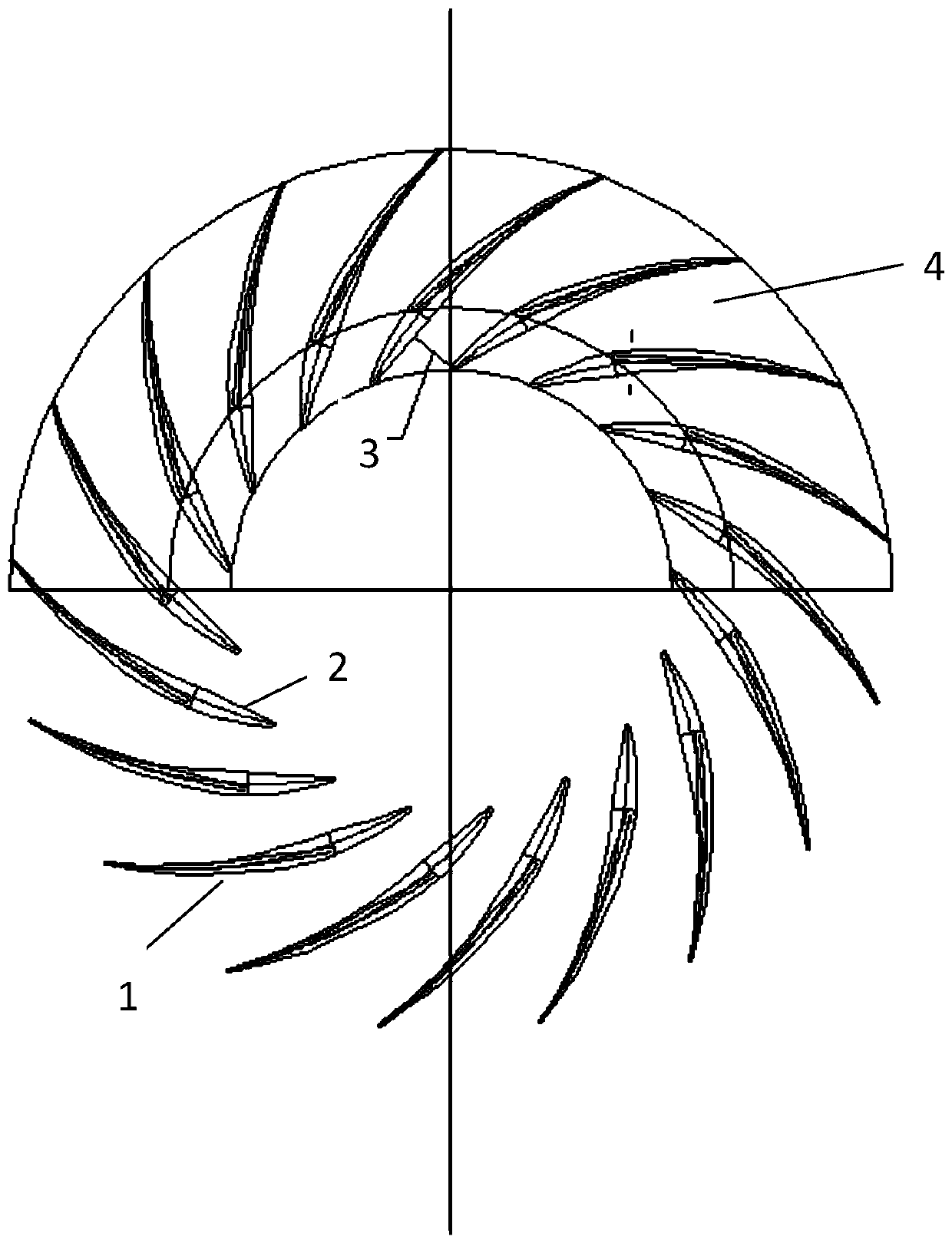
[0032] Such as figure 1 As shown, the present invention provides a vane diffuser, the vane diffuser is composed of two sections of airfoil-shaped composite blades, and the circumference is evenly distributed in the flow channel of the diffuser body 4 to form two sections of composite airfoil-shaped blades Diffuser form.

[0033] Further, the blade is a two-section airfoil blade as a whole, the front section blade 1 adopts a half-height blade and the rear section blade 2 is a composite airfoil blade with a full height blade, and the joint position of the front and rear sections is at the throat of the diffuser channel After 3, the rear half of the airfoil blade head adopts a new airfoil design, which solves the limitation that the number of blade airfoils is difficult to arrange reasonably, and has the advantage of high efficiency and low cost.

[0034] Furthermore, the half-height section of the blade head of the composite airfoil diffuser can be installed on the disk side or...


PUM


Abstract

The invention provides a composite blade and a compressor blade diffuser. The blade comprises a unique blade type and a circumferential uniform arrangement type of a composite blade, the whole blade is a two-section wing-shaped blade, the front half section adopts a half-height blade and the rear half section adopts a full-height blade, the combination position of the front section and the rear section is behind the throat position of a diffuser channel, and the head of the rear half section of the wing-shaped blade adopts a brand-new wing-shaped design. According to the blade type, the problems of the blade diffuser number design and over large blade diffuser blocking flow are improved, the design has the advantage of wide stable working condition range of a half-height type diffuser andthe advantage of machining and manufacturing of a binary blade diffuser, the blade is still the binary blade, and the machining and mounting difficulty is effectively reduced.

Description

technical field [0001] The invention relates to a diffuser structure, in particular to a blade diffuser of a centrifugal compressor. Background technique [0002] In a centrifugal compressor, the main function of the diffuser is to increase the gas pressure by reducing the airflow velocity at the outlet of the impeller. The energy loss of the airflow in the diffuser accounts for most of the loss of the static components of the centrifugal compressor. At the same time, it affects the overall structure of the compressor and aerodynamic performance is greatly affected. [0003] Common diffusers are divided into vaneless diffusers, vane diffusers and straight wall diffusers. The vaneless diffuser has simple structural design and manufacturing, and the airflow direction angle α is basically unchanged, but its airflow flow is long, the flow loss is large, and the diffusion efficiency is low. The shape and installation of the vane in the vane diffuser promotes the gradual increas...

Claims


Application Information

Patent Timeline
Patent Type & Authority Applications(China)
IPC IPC(8): F04D29/44
CPCF04D29/444
Inventor 周向民李宏安贾亚妮蒋荣辉段纪成程凯史军党
Owner SHAANXI BLOWER GROUP
Why Eureka
Try Eureka