Fan runner plate, deformation control method thereof and fan

A flow channel plate and fan technology, which is applied to non-variable-capacity pumps, components of pumping devices for elastic fluids, machines/engines, etc. Increase the risk of friction between the fan blade and the fan runner plate, and increase the flow loss at the root of the fan, so as to improve the flow loss, reduce the risk of collision, and avoid non-uniform wear.

Pending Publication Date: 2022-04-12
AECC COMML AIRCRAFT ENGINE CO LTD
View PDF0 Cites 0 Cited by
  • Summary
  • Abstract
  • Description
  • Claims
  • Application Information

AI Technical Summary

Problems solved by technology

[0005] 2) Due to the limitation of the structure of the fan flow channel plate, both sides of the flow channel surface need to cooperate with the surface profile of the fan blade pressure surface and the suction surface flow channel line respectively. The fan flow channel plate is asymmetrical about the central plane, and the fan flow channel There is a circumferential eccentricity between the center of mass of the plate and the axis of rotation. During the working process, the radial deformation of the convex side of the fan flow channel plate is much larger than the radial deformation of the concave side of the flow channel surface. The radial deformation of the flow channel surface of the fan flow channel plate The distribution gradient of the deformation in the circumferential direction is relatively large, which will increase the leakage loss caused by the radial non-uniform deformation of the fan flow channel surface, increase the flow loss at the root of the fan, and increase the non-uniformity of the pressure surface and suction surface of the fan blade Wear and tear, increasing the risk of rubbing between the fan blades and the fan runner plate

Method used


Image

  • Fan runner plate, deformation control method thereof and fan
  • Fan runner plate, deformation control method thereof and fan
  • Fan runner plate, deformation control method thereof and fan

Examples


Embodiment Construction

[0031] A variety of different implementations or examples for implementing the described subject technical solutions are disclosed below. In order to simplify the disclosure, the following describes the specific examples of each component and arrangement, of course, these are only examples, not limiting the protection scope of the present invention. For example, the description that the first feature described later in the description is formed on or above the second feature may include an embodiment in which the first and second features are formed through direct contact, and may also include an embodiment in which the first and second features are formed between the first and second features. Embodiments of additional features such that there may be no direct relationship between the first and second features. Additionally, reference numerals and / or letters may be repeated in different instances in these disclosures. This repetition is for brevity and clarity and does not i...


PUM


Abstract

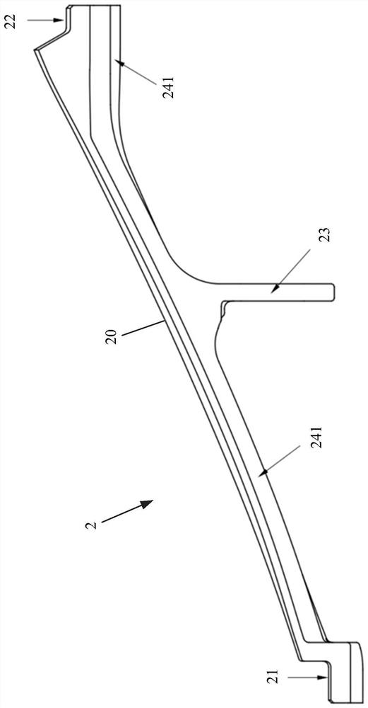
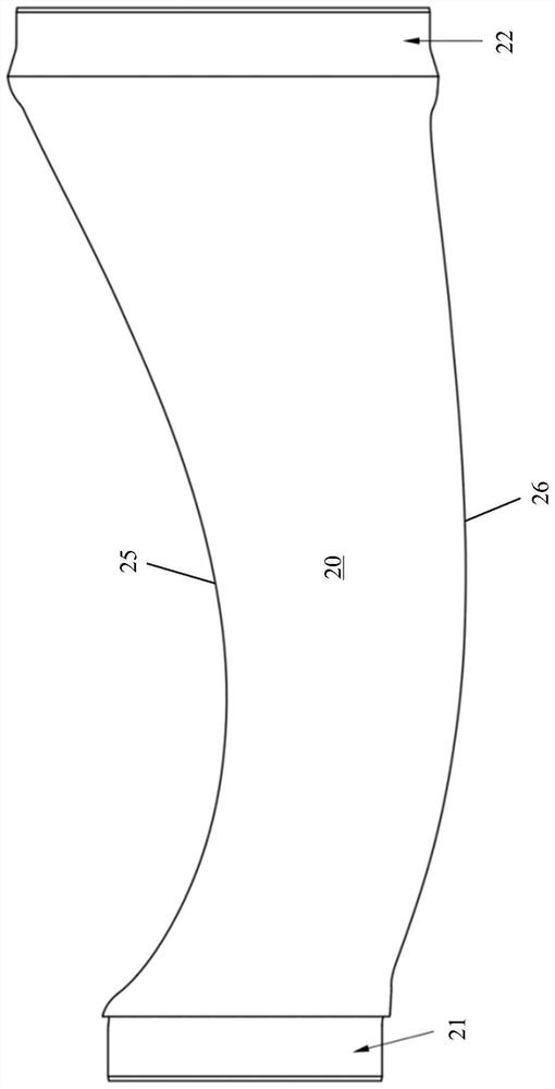
The invention provides a fan runner plate and a deformation control method thereof and a fan, the fan runner plate is provided with a runner surface on the outer side, axial reinforcing ribs on the inner side, a first molded surface matching side on one side in the circumferential direction and a second molded surface matching side on the other side in the circumferential direction, the fan runner plate is further provided with a mass center, a rotating axis and a central plane, the mass center is on one side of the central plane, and the rotating axis is on the other side of the central plane. The axial reinforcing ribs comprise the first axial reinforcing rib and the second axial reinforcing rib, the distance between the mass center and the first axial reinforcing rib is smaller than that between the mass center and the second axial reinforcing rib, and the thickness of the second axial reinforcing rib is smaller than that of the first axial reinforcing rib. From the first molded surface matching side to the second molded surface matching side, the radial rigidity of the fan runner plate is uniformly distributed by taking the rotating axis as a reference, so that the radial deformation of the runner surface in the working process is uniformly distributed in the circumferential direction.

Description

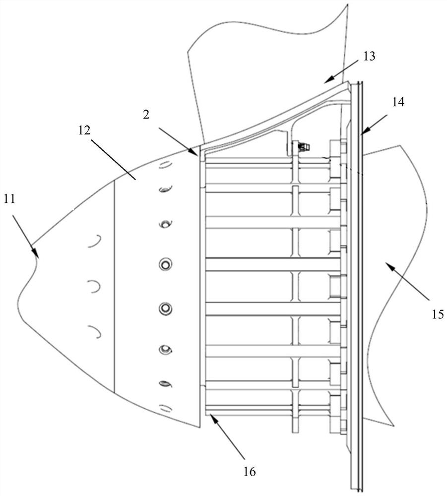
technical field [0001] The invention relates to a fan channel plate of a turbofan engine and a deformation control method thereof. Background technique [0002] The structure of the fan part of the axial flow aircraft engine is as follows: figure 1 As shown, it mainly includes the front section 11 of the intake cone, the rear section 12 of the intake cone, the fan disk 16 , the runner plate 2 , the fan blade 13 , the sealing ring 14 and the drum 15 . The flow channel plate 2 is installed between the fan blades 13, and forms the flow channel of the engine intake section with the front section 11 of the intake cone, the rear section 12 of the intake cone and the sealing ring 14. Usually, sealing strips are arranged on both sides of the flow channel plate 2 to prevent Gas leaks from the gap between the fan blade 13 and the flow channel plate 2 . [0003] The inventor has found through research: [0004] 1) During the operation of the aero-engine, the fan flow channel plate i...

Claims


Application Information

Patent Timeline
Patent Type & Authority Applications(China)
IPC IPC(8): F04D29/32F04D29/54F04D29/66
Inventor 覃文源喻思谭焕成陈璐璐
Owner AECC COMML AIRCRAFT ENGINE CO LTD
Why Eureka
Try Eureka