Gas sensor

a technology of gas sensor and sensor element, which is applied in the field of sensor element, can solve the problems of inability to detect gas in the sensor element, and achieve the effects of improving manufacturing efficiency, high hardness, and reducing manufacturing process

Active Publication Date: 2020-12-29
NGK SPARK PLUG CO LTD
View PDF8 Cites 1 Cited by
  • Summary
  • Abstract
  • Description
  • Claims
  • Application Information

AI Technical Summary

Benefits of technology

[0011]In view of the foregoing, it is an object of the present invention to provide a sensor element capable of setting the oxygen concentration of a reference electrode to a value different from that of the air and, at the same time, ensuring a stable gas detection output of the sensor element. It is also an object of the present invention to provide a gas sensor with the sensor element and a method of manufacturing the sensor element.
[0015]In the above manufacturing method, the green lead and the green through hole conductor can be formed integral with each other in the same step for reduction in manufacturing process and improvement in manufacturing efficiency.
[0016]During the manufacturing of the sensor element, the green second ceramic layer of relatively high hardness is stacked on the conductive paste layer for formation of the reference lead. The through hole conductor and a part of the conductive paste layer in the vicinity of the through hole conductor may be hence compressed and deformed by the green second ceramic layer. In the present invention, however, the material of the ventilation portion is provided on a surface of the conductive paste layer in the vicinity of the through hole conductor so as to avoid direct contact of the green second ceramic layer with the through hole conductor and the conductive paste layer. The through hole conductor and the conductive paste layer are thus prevented from being compressed and deformed to a smaller thickness than the material of the ventilation portion. The reference lead, when formed by firing the conductive paste layer, does not vary in oxygen permeability so that the gas detection output of the sensor element does not become unstable due to variations in the oxygen permeability of the reference lead. Further, the reference lead is exposed to and in communication with the ventilation portion so that oxygen can be reliably discharged from the reference lead to the through hole through the ventilation portion. This makes it possible to set the oxygen concentration of the reference electrode to a value different from the oxygen concentration of the air and to ensure the stable gas detection output of the sensor element.
[0017]In the presence of the ventilation portion, the bottom of the through hole in the vicinity of the reference lead is increased in diameter and internal volume so that water entering in the ventilation portion or the reference lead can be easily discharged to the outside through the through hole. The reference lead is thus prevented from being clogged with such entering water to cause a deterioration of oxygen permeation. This also makes it possible to ensure the stable gas detection output of the sensor element.

Problems solved by technology

This results in an unstable gas detection output of the sensor element 1100.

Method used


Image

  • Gas sensor
  • Gas sensor
  • Gas sensor

Examples


first embodiment

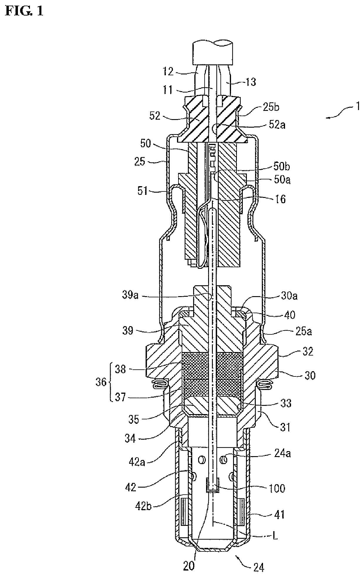
[0033]A gas sensor 1 according to the present invention will be first explained below with reference to FIGS. 1 to 5.

[0034]FIG. 1 is a cross-sectional view of the gas sensor 1 as taken along the direction of an axis L thereof (also referred to as “longitudinal direction” or “axis direction”). In the first embodiment, the gas sensor 1 is configured as an oxygen sensor. Referring to FIG. 1, the gas sensor 1 includes: a stacked-type sensor element 100 having a rectangular plate shape extending in the direction of the axis L; a metal shell 30 holding therein the sensor element 100; and a protector 24 fitted on a front end portion of the metal shell 30. A porous protection layer 20 is formed to cover the entire circumference of a front end part of the sensor element 100.

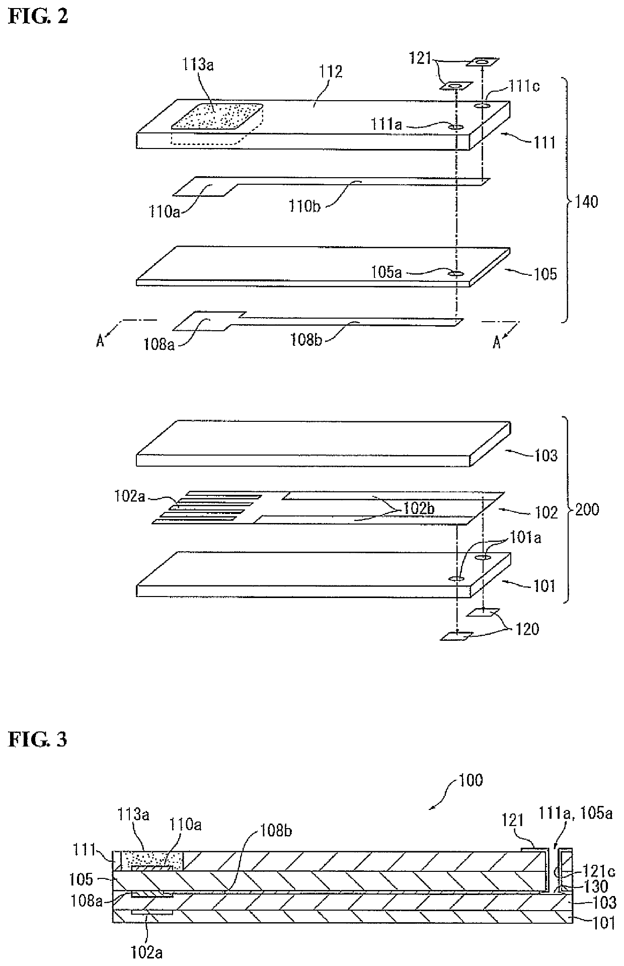
[0035]FIG. 2 is an exploded perspective view of the sensor element 100. Referring to FIG. 2, the sensor element 100 has a single-cell structure that includes an oxygen concentration detection cell 140 and a heater 200 sta...

second embodiment

[0080]Although not specifically shown in the drawings, two other through holes are respectively formed in the solid electrolyte body 165 and the protection layer 167; and through hole conductors are disposed on inner walls of these through holes so as to electrically connect rear terminals of the leads for the first and second pumping electrodes 162a and 163a to sensor element-side pads 169. In the second embodiment, the second through hole 105a, the third through hole 111a, the fourth through hole 165a and the fifth through hole 166a correspond to the claimed through hole.

[0081]In the sensor element 100B, the direction and magnitude of current flowing between the electrodes 162a and 163a of the oxygen pumping cell 150 are adjusted such that the voltage (electromotive force) developed between the electrodes of the oxygen concentration detection cell 140 becomes constant at a predetermined value (e.g. 450 mV). The sensor element 100B is hence configured to detect the oxygen concentra...


PUM

PropertyMeasurementUnit
thicknessaaaaaaaaaa
temperatureaaaaaaaaaa
voltageaaaaaaaaaa

Abstract

Disclosed is a stacked-type plate-shaped sensor element for detecting the concentration of a specific gas component in a gas under measurement. The sensor element includes: a first ceramic layer; a pair of measurement and reference electrodes stacked on a front end part of the first ceramic layer; a through hole formed through at least the first ceramic layer in a rear end side of the sensor element; a through hole conductor disposed on an inner wall of the through hole; a porous reference lead extending between the reference electrode and the through hole conductor; a gas-impermeable second ceramic layer arranged on the first ceramic layer to cover at least the reference lead; and a ventilation portion provided, in the form of a hollow space or a porous substance, between the first and second ceramic layers at a position facing the through hole and communicating with the reference lead.

Description

FIELD OF THE INVENTION[0001]The present invention relates to a sensor element for detecting the concentration of a specific gas component in e.g. a combustion gas or exhaust gas of a combustion device, internal combustion engine or the like. The present invention also relates to a gas sensor equipped with the sensor element and a method of manufacturing the sensor element.[0002]Hereinafter, the term “front” refers to a gas sensing side with respect to the direction of an axis of a gas sensor (sensor element); and the term “rear” refers to a side opposite the front side.BACKGROUND OF THE INVENTION[0003]There is conventionally used a gas sensor for detecting the concentration of a specific gas component such as oxygen in an exhaust gas of an internal combustion engine, which has installed therein a sensor element including a plate-shaped solid electrolyte body and at least a pair of electrodes arranged on the solid electrolyte body.[0004]Japanese Patent No. 4897912 (hereinafter abbrev...

Claims


Application Information

Patent Timeline
Patent Type & Authority Patents(United States)
IPC IPC(8): G01N27/407G01N27/406
CPCG01N27/4067G01N27/407G01N27/4062G01N27/4071
Inventor SHIMIZU, YASUMITSUKITO, TAKAYUKI
Owner NGK SPARK PLUG CO LTD
Why Eureka
Try Eureka