Device for producing rhythmic movement and vibrating bed having the same

a technology of rhythmic movement and vibrating bed, which is applied in the direction of beds, springs/dampers, physical therapy, etc., can solve the problems of social population becoming elderly, slowing down of national health rate year by year, and elderly people often unable to exercise, so as to achieve smooth reciprocation of load-bearing members

Active Publication Date: 2021-01-05
TUNG KENG ENTERPRISE CO LTD
View PDF10 Cites 0 Cited by
  • Summary
  • Abstract
  • Description
  • Claims
  • Application Information

AI Technical Summary

Benefits of technology

[0007]In view of the above, the primary objective of the present invention is to provide a device for producing a rhythmic movement, which could be applied to a load-bearing member and could smoothly reciprocate the load-bearing member.
[0009]In addition, the another primary objective of the present invention is to provide a vibrating bed, which could be smoothly reciprocated.
[0011]With the aforementioned design, the disclosure of the present invention could smoothly reciprocate the vibrating bed or the load-bearing member.

Problems solved by technology

Long-term lack of exercise makes people prone to chronic diseases, leading to a decline in the national health rate year by year.
On the other hand, the social population has become elderly in recent years, and older people are often unable to exercise due to joint aging.
While switching the reciprocating direction, the rotation of the wheel is not easy to be smooth, so that the reciprocation is not smooth either, which may even cause equipment damage and increase maintenance cost.
However, using the connecting shaft to achieve a reciprocating motion consumes too much kinetic energy on the connecting shaft, so that such reciprocating device has a large power consumption, which is not environmentally friendly.

Method used


Image

  • Device for producing rhythmic movement and vibrating bed having the same
  • Device for producing rhythmic movement and vibrating bed having the same
  • Device for producing rhythmic movement and vibrating bed having the same

Examples


Embodiment Construction

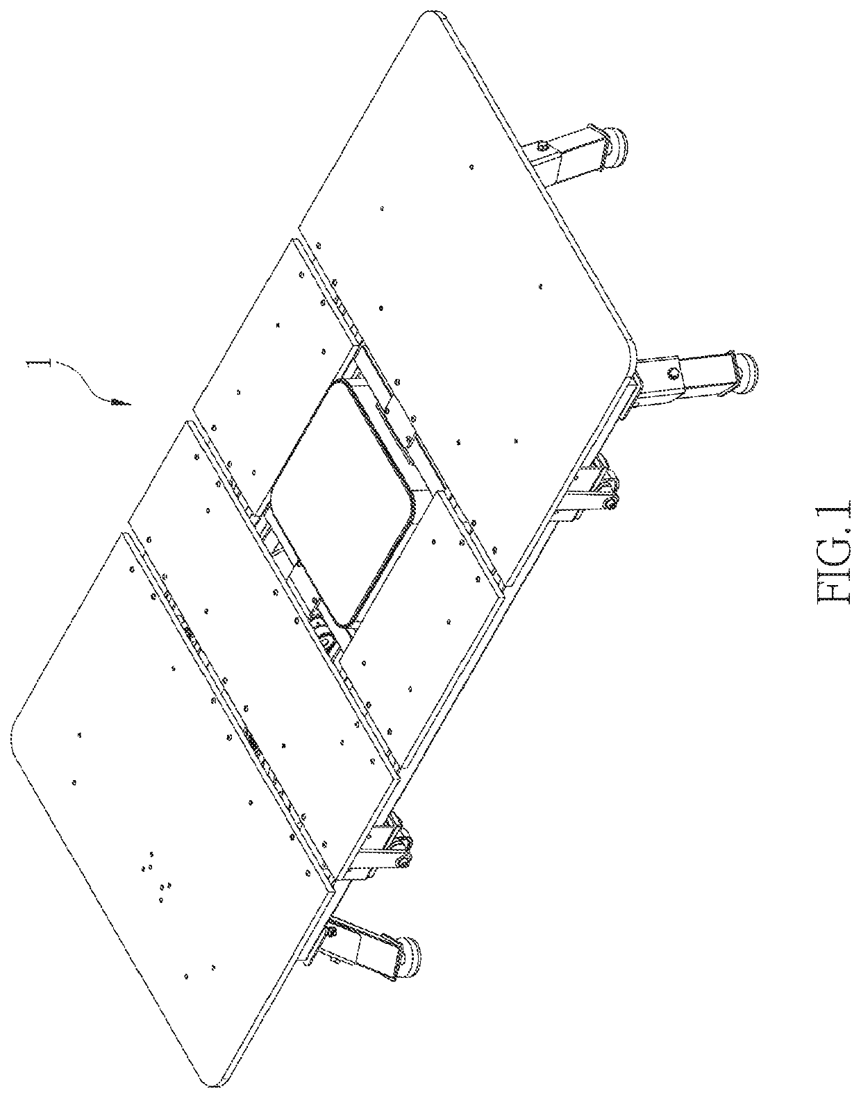
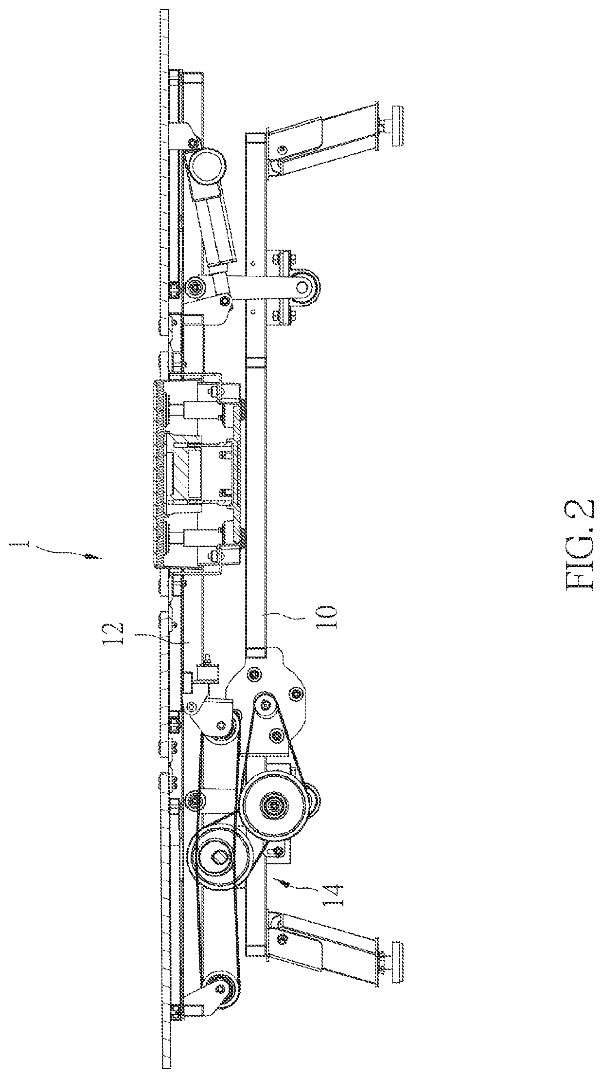
[0021]FIG. 1 is a schematic diagram of a vibrating bed 1 of an embodiment according to the present invention, and FIG. 2 is a sectional view of the vibrating bed 1 shown in FIG. 1. As shown in FIG. 1 and FIG. 2, the vibrating bed 1 includes a fixed base 10, a movable base 12, and a reciprocating device 14 which is disposed between the fixed base 10 and the movable base 12 for producing a rhythmic movement. In the current embodiment, the vibrating bed 1 could be used as a bed for medical treatment or health care, which allows the user to lie on it to be horizontally moved in a reciprocating manner. However, the vibrating bed 1 the current embodiment is not limited to be a vibrating bed for medical treatment or health care, but could be any load-bearing member with a similar structure or function. In practice, the vibrating bed 1 could also have a vertical vibration function.

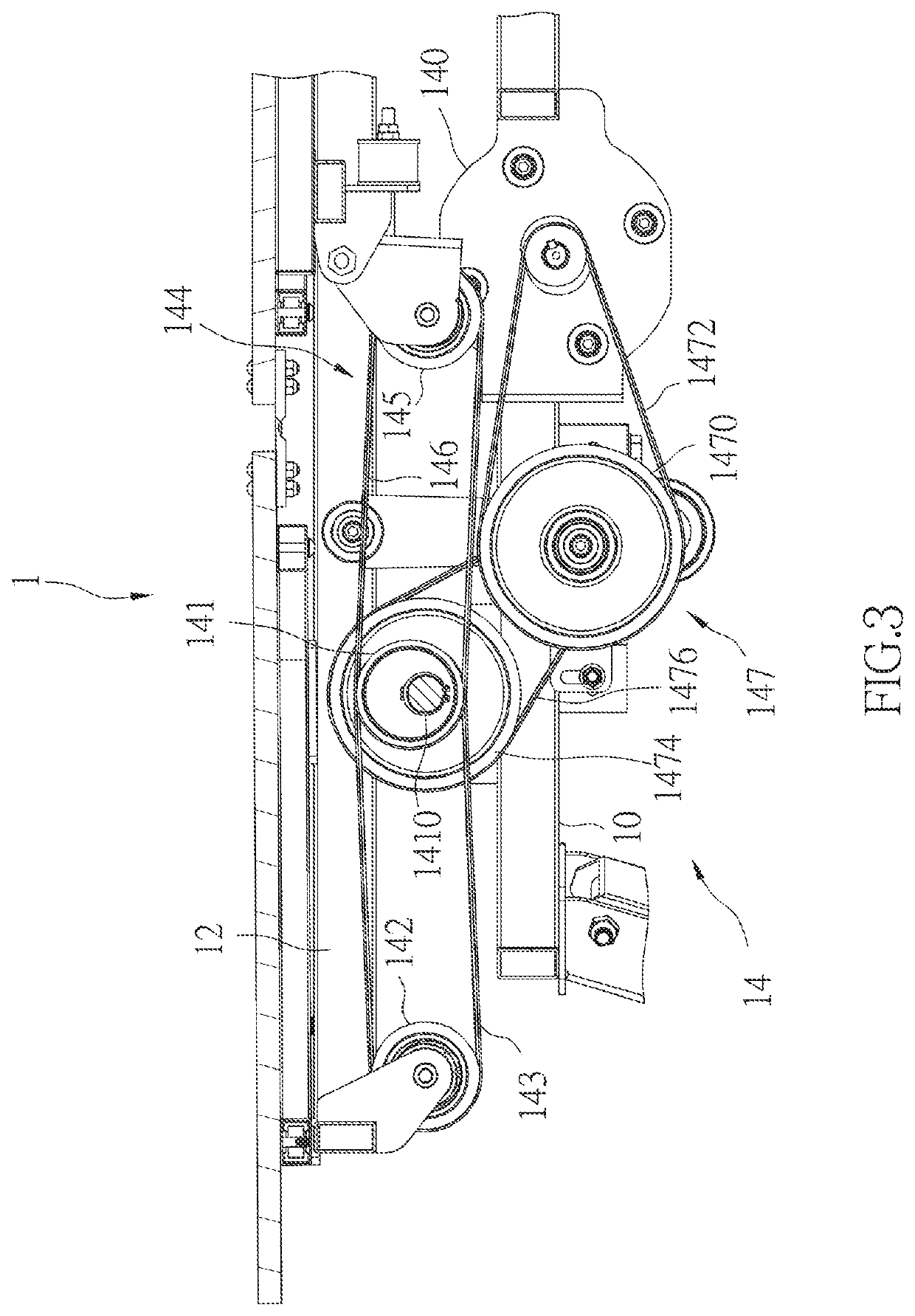
[0022]FIG. 3 is a partially schematic diagram of the vibrating bed 1 shown in FIG. 2, and FIG. 4 is a partially...


PUM


Abstract

A reciprocating device applied to a load-bearing member includes a motor, an eccentric wheel, a first pulley disposed on a movable base of the load-bearing member, a first belt, and a recovery mechanism disposed on the movable base. The motor and the eccentric wheel are disposed on a fixed base of the load-bearing member. The eccentric wheel is connected to the motor to be driven to rotate around an eccentric shaft of the eccentric wheel. The first belt surrounds the eccentric wheel and the first pulley. The eccentric wheel is operatively coupled to the first pulley via the first belt. When the eccentric wheel is rotated by the motor, the first pulley and the movable base connected to the first pulley is operatively coupled to the eccentric wheel. The recovery mechanism provides a reverse force to the movable base according to said linkage.

Description

BACKGROUND OF THE INVENTIONTechnical Field[0001]The present invention relates generally to a reciprocating device and a vibrating bed, and more particularly to a device for producing a rhythmic movement, which allows a load-bearing member to reciprocate, and a vibrating bed with the device for producing a rhythmic movement.Description of Related Art[0002]Modern people are busy and their exercise time is relatively reduced. Long-term lack of exercise makes people prone to chronic diseases, leading to a decline in the national health rate year by year. On the other hand, the social population has become elderly in recent years, and older people are often unable to exercise due to joint aging. Therefore, some manufacturers in the industry have developed a bed that can perform vertical or horizontal vibrations, so that people who do not exercise regularly or are unable to exercise can exercise at rest.[0003]A conventional reciprocating device is disposed under a mattress of a horizontal...

Claims


Application Information

Patent Timeline
Patent Type & Authority Patents(United States)
IPC IPC(8): A47C21/00F16F15/04F16F15/12
CPCA47C21/006F16F15/046F16F15/1206A61H2201/0142A61H2201/1215A61H2201/1673
Inventor HUANG, CHIA-YEN
Owner TUNG KENG ENTERPRISE CO LTD
Why Eureka
Try Eureka