
Sheet post-processing apparatus and image formation system using the apparatus

a post-processing apparatus and post-processing technology, applied in the field of sheet post-processing apparatus, can solve the problems of troublesome maintenance space, difficult to find the correct processing position, etc., and achieve the effect of convenient recovery work, small and compact apparatus, and convenient maintenance spa

Active Publication Date: 2014-09-02
NISCA KK
View PDF4 Cites 0 Cited by
  • Summary
  • Abstract
  • Description
  • Claims
  • Application Information

AI Technical Summary

Benefits of technology

The invention is a machine that guides sheets of material from a discharge path to a processing tray. It uses a pair of guide members that shift and move in the same way as a pair of side edge alignment members, which are also in the processing tray. This design makes the machine small and compact, and helps to align the sheet width direction without the need for multiple parts. The guide members are made of metal or resin to ensure smooth guiding of the sheet and to prevent misalignment. A roller holder is also included to keep a sheet discharge roller in contact with the sheet, preventing rattling during movement. Overall, this invention simplifies the machine's construction, reduces space requirements, and improves its efficiency and ease of maintenance.

Problems solved by technology

Then, the sheet that is carried onto the tray is positioned and aligned in the front and back in the sheet discharge direction and the left and right in the sheet-discharge orthogonal direction to reference positions, and therefore, it is difficult to find a correct processing position.
However, it has a problem with space providing a retract mechanism for retracting a plurality of members inside limited space of the sheet discharge path and processing tray, and at the same, the problem arises that maintenance space when trouble occurs is not obtained.

Method used


Image

  • Sheet post-processing apparatus and image formation system using the apparatus
  • Sheet post-processing apparatus and image formation system using the apparatus
  • Sheet post-processing apparatus and image formation system using the apparatus

Examples


Embodiment Construction

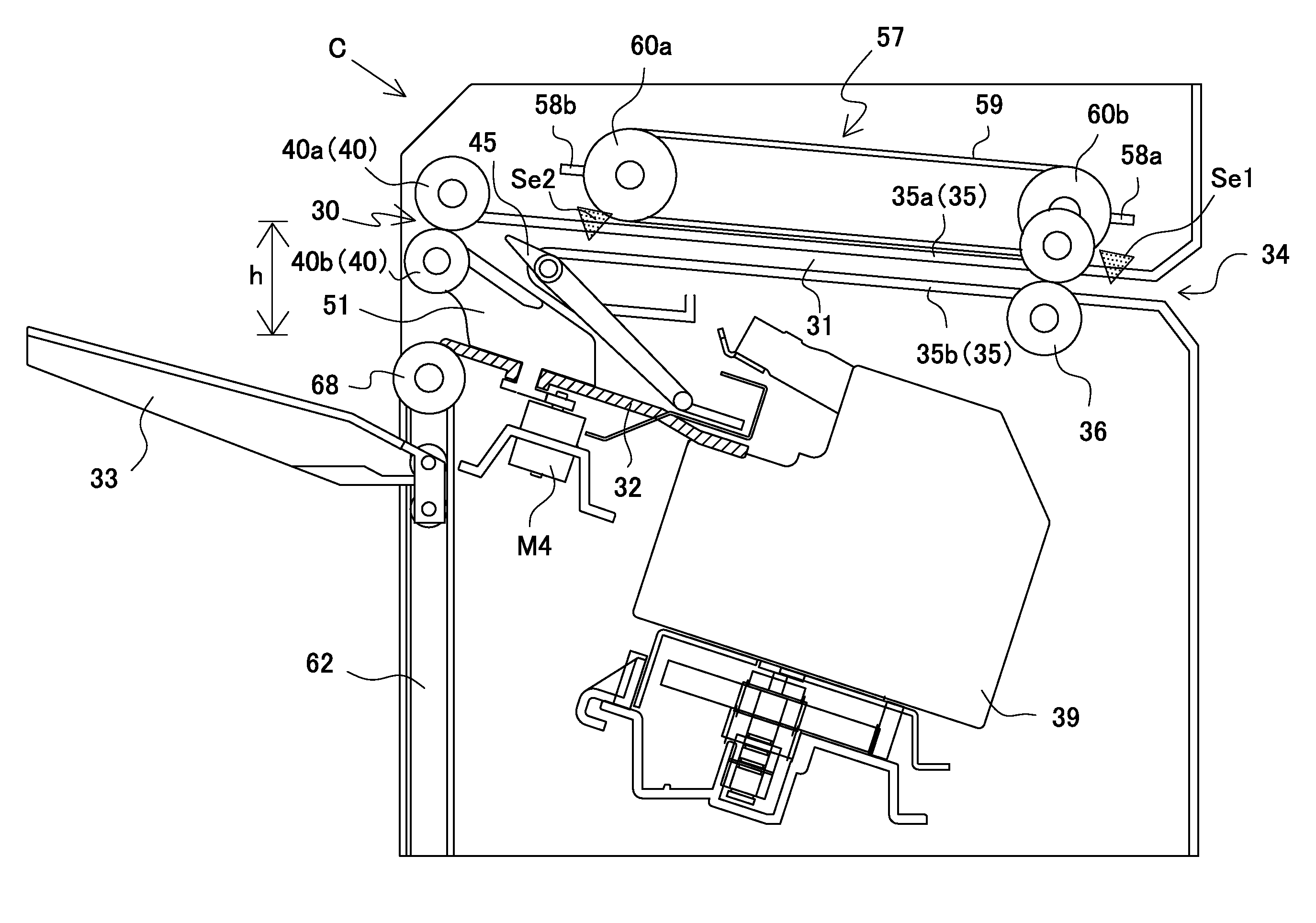
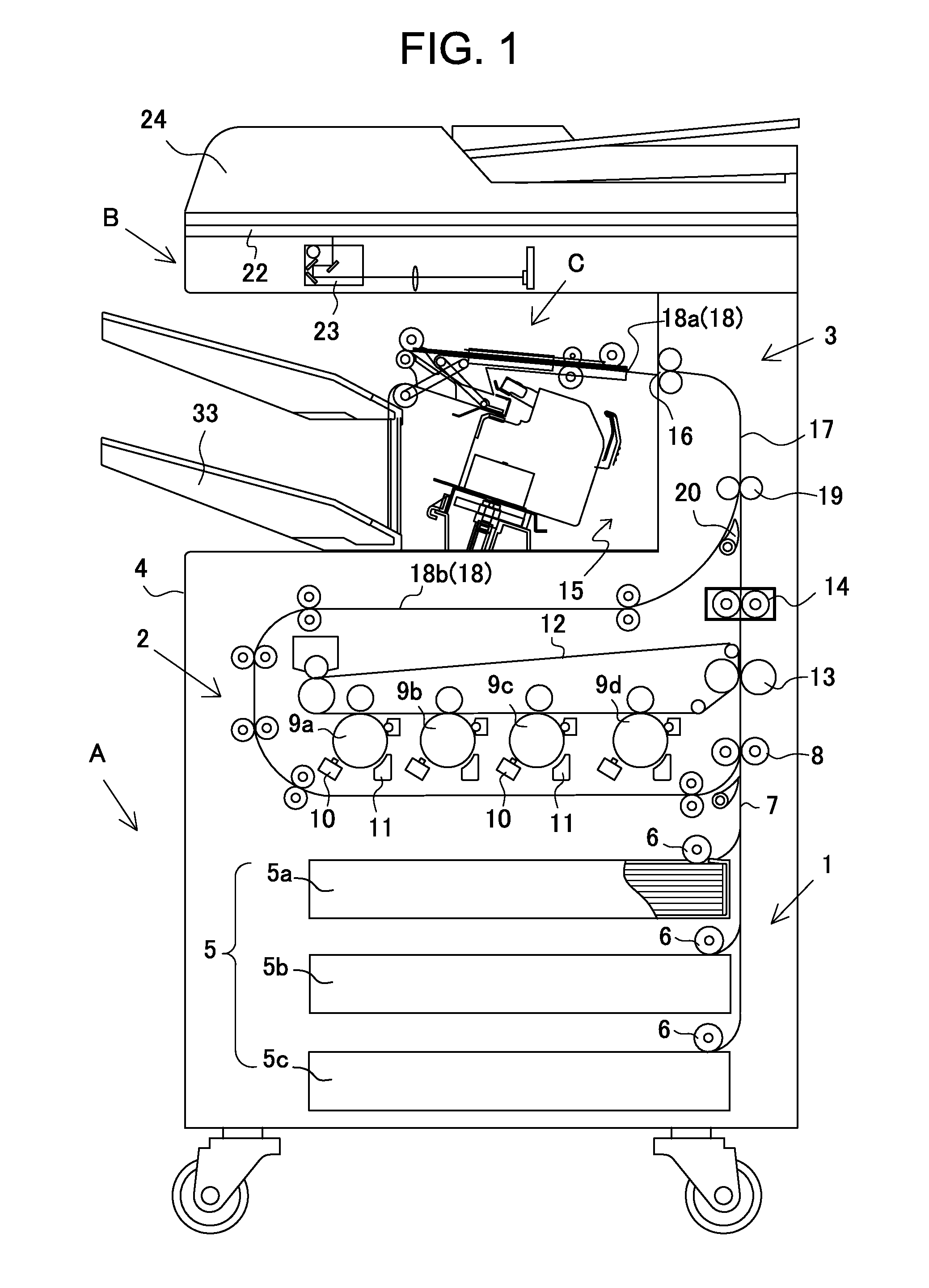
[0034]The present invention will specifically be described below according to preferred Embodiments shown in drawings. FIG. 1 shows an image formation system according to the invention. This system is comprised of an image formation unit A, image read unit B and post-processing unit C. Then, the image read unit B reads an original image, and based on the image data, the image formation unit A forms the image on a sheet. Then, the post-processing unit C performs finish processing such as binding processing on image-formed sheets.

[0035]The post-processing unit C shown in the figure is inserted in a sheet discharge area 15 of the image formation unit A, and is configured as an apparatus which collates and collects image-formed sheets to perform binding processing. Further, the image read unit B is mounted above the image formation unit A, and the post-processing unit C is disposed in between both units.

[0036]Alternatively, it is also possible to configure the image formation unit A, im...


PUM

PropertyMeasurementUnit
heightaaaaaaaaaa
widthaaaaaaaaaa
distanceaaaaaaaaaa

Abstract

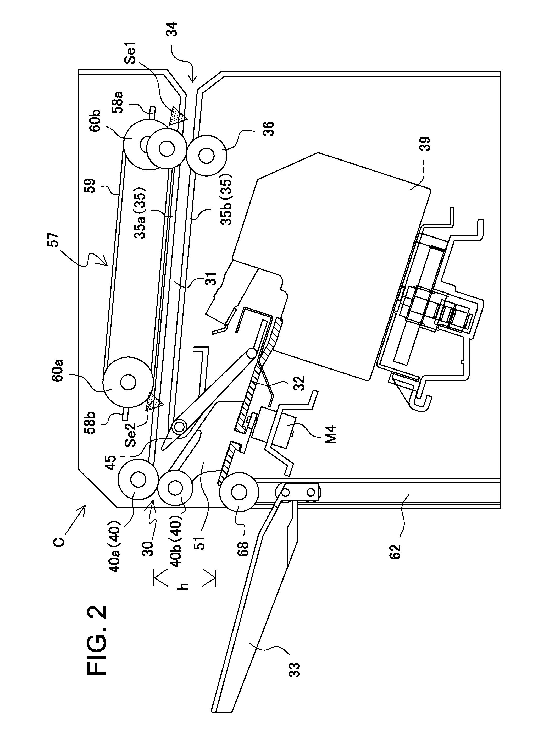
To provide a post-processing apparatus for preventing a sheet from becoming misaligned in dropping the rear end side of the sheet carried in a processing tray from a sheet discharge path to store on the tray, and enabling the mechanism to be simplified, compact and configured at low cost, a sheet guide that guides a sheet from the sheet discharge path to the processing tray is comprised of a pair of right and left guide members, at the same time in the processing tray are disposed a pair of right and left side edge alignment members, and each guide member and each side edge alignment member are configured to shift to positions in the sheet width direction in an integral manner using a common drive motor.

Description

BACKGROUND OF THE INVENTION[0001]The present invention relates to a sheet post-processing apparatus for feeding an image-formed sheet to a processing tray to perform post-processing, and then storing the sheet in a stack tray, and more particularly, improvements in a sheet transport mechanism for feeding and setting a sheet in a processing position on the processing tray with a correct posture.[0002]Generally, this kind of post-processing apparatus is known as an apparatus which is connected to a sheet discharge outlet of an image formation apparatus, collates and collects image-formed sheets on a processing tray to perform post-processing such as binding processing, punching processing and stamping processing, and stores the processed sheets in a stack tray.[0003]For example, Patent Document 1 discloses an apparatus which transports backward a sheet fed from an image formation apparatus to a processing tray disposed below a sheet discharge outlet, performs binding processing with a...

Claims


Application Information

Patent Timeline
Patent Type & Authority Patents(United States)
IPC IPC(8): B65H31/36B65H31/00B65H29/14B65H29/34B65H31/10B65H31/20B65H31/30B65H31/34B65H31/38
CPCB65H29/14B65H31/38B65H31/3027B65H31/10B65H29/34B65H31/34B65H31/20B65H2404/166B65H2553/83B65H2404/1523B65H2553/612B65H2801/27B65H2404/232B65H2404/1521B65H2404/731B65H2301/4212B65H2301/4213B65H2404/742B65H9/101B65H2403/411B65H2404/242B65H2553/61
Inventor MAEJIMA, HIROSHIAKIYAMA, HIROTO
Owner NISCA KK
Learn More