Eureka AIR delivers breakthrough ideas for toughest innovation challenges, trusted by R&D personnel around the world.

Synchronization method and controller

a synchronization method and controller technology, applied in the direction of generating/distributing signals, electric programme control, pulse automatic control, etc., can solve problems such as errors between signals, and achieve the effect of reducing synchronization accuracy and high accuracy

Active Publication Date: 2021-01-05
FANUC LTD
View PDF6 Cites 0 Cited by
  • Summary
  • Abstract
  • Description
  • Claims
  • Application Information

AI Technical Summary

Benefits of technology

The patent describes a way to make sure that a communication control circuit and a basic timing signal generation circuit can work together accurately, even if they are using different clocks. This can be useful when working with external equipment.

Problems solved by technology

As the basic timing signal and the communication cycle timing signal are based on different clocks, however, error may be caused between these signals due to the foregoing accuracy error between the clocks.

Method used


Image

  • Synchronization method and controller
  • Synchronization method and controller
  • Synchronization method and controller

Examples


first embodiment

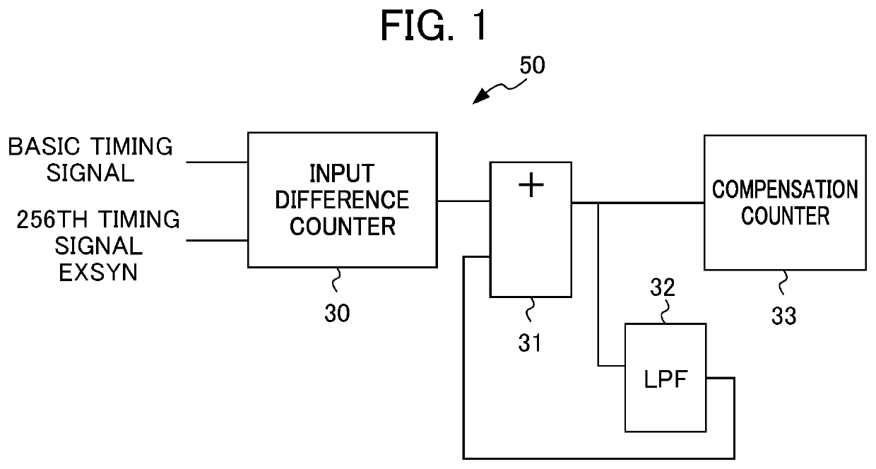
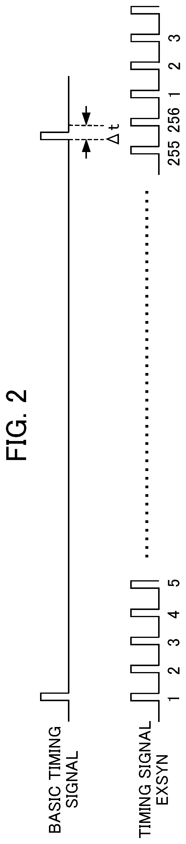
[0057]According to the first embodiment, a synchronous circuit 100 of the communication control circuit 3 includes a compensation timing averaging circuit. If error between a basic timing signal and the 256th timing signal EXSYN is less than 256 clocks, for example, the compensation timing averaging circuit is used for eliminating this error. This allows the timing signal EXSYN to be compensated for on average in the interval of the basic timing signal (4 ms).

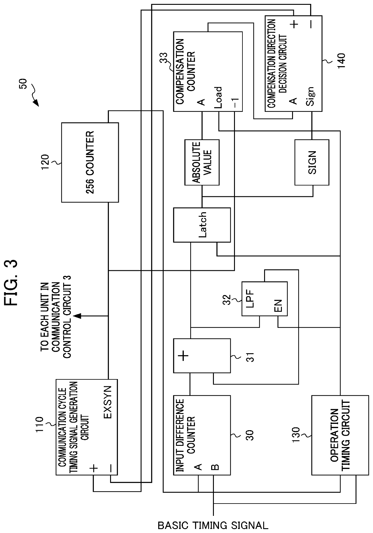
[0058]An outline of the first embodiment will be described first. According to the first embodiment, the synchronous circuit 100 of the communication control circuit 3 includes the compensation timing averaging circuit that divides a compensation value responsive to an input difference measured by an input difference counter by the number of the timing signals EXSYN generated in the interval of the basic timing signal, adds up a value resulting from the division in each communication cycle, and compensates for timing of generat...

second embodiment

[0076]In comparison to the foregoing, if a controller 1A makes Ethernet (registered trademark) synchronization of a basic timing signal with a different controller 1B, for example, trying to make the basic timing signal follow a basic timing signal from the different controller 1B may cause significant error of input of the basic timing signal to be input to the communication control circuit 3 from a 256th timing signal EXSYN. In some cases, this may require the synchronous circuit 100 of the communication control circuit 3 to take time in eliminating this error equal to or longer than the interval (4 ms) of the basic timing signal. In this regard, even in the presence of the compensation timing averaging circuit (dividing circuit 200 and adding circuit 210) of the first embodiment, the synchronous circuit 100 is still caused to always follow the basic timing signal, causing accumulation of synchronization error due to accuracy error of clocks between the communication control circu...


PUM


Abstract

According to a synchronization method, a basic timing signal generation circuit generates a basic timing signal. A communication control circuit generates a first communication cycle timing signal, measures an input difference between the basic timing signal and a predetermined one of first communication cycle timing signals, divides a compensation value responsive to the input difference by the number of first communication cycle timing signals, adds up a value resulting from the division in a communication cycle, compensates for timing of generating the first communication cycle timing signal with timing equal to or greater than a predetermined value, and transmits timing compensation data to external equipment. The external equipment generates a second communication cycle timing signal, compensates for timing of generating the second communication cycle timing signal based on timing of receipt of the timing compensation data, and synchronizes with the first communication cycle timing signal.

Description

[0001]This application is based on and claims the benefit of priority from Japanese Patent Application No. 2019-145463, filed on 7 Aug. 2019, the content of which is incorporated herein by reference.BACKGROUND OF THE INVENTIONField of the Invention[0002]The present invention relates to a synchronization method and a controller.Related Art[0003]A numerical controller makes real-time communication to control the position, speed, etc. of each of a plurality of motors such as a servo motor included in a machine tool or a robot, for example, thereby performing machining into a complicated shape, etc. This requires highly accurate synchronization between a communication cycle timing signal generated in each communication cycle by a communication control circuit included in the numerical controller and a communication cycle timing signal generated by an amplifier of each motor. The communication cycle timing signal from the communication control circuit is also required to be synchronized ...

Claims


Application Information

Patent Timeline
Patent Type & Authority Patents(United States)
IPC IPC(8): H03L7/06G06F1/14G06F1/12G06F1/06
CPCH03L7/06G06F1/06G06F1/12G06F1/14G05B19/414H03K5/135H03K23/662
Inventor NAKAMA, TOMOMASA
Owner FANUC LTD
Why Eureka
Eureka Blog
Learn More