Check patentability & draft patents in minutes with Patsnap Eureka AI!

Temporal alignment of and signal-to-noise-ratio enhancment in image streams for multi-channel x-ray imaging

a multi-channel x-ray imaging and image stream technology, applied in the field of image processing apparatus, can solve the problems of image artifacts that affect the processing effect, and achieve the effect of reducing artifacts, reducing temporal distance, and reducing processing errors

Active Publication Date: 2021-01-05
KONINKLJIJKE PHILIPS NV
View PDF17 Cites 0 Cited by
  • Summary
  • Abstract
  • Description
  • Claims
  • Application Information

AI Technical Summary

Benefits of technology

[0014]According to one embodiment, the apparatus operates to estimate or interpolate across time (temporally) from two frames in the same channel. The temporal interpolation uses a combination of motion-estimation and in one embodiment soft-thresholding to achieve an accurate estimate for the interpolated frame from two acquired frames. Because of the aligning in time (temporally aligning) of actual frames and estimated frames, a temporal distance between two (or more) channels can be effectively nullified thereby eliminating or at least reducing artifacts caused by the temporal distance. In the past there were efforts to reduce the temporal distance. However, with the apparatus as proposed herein, even large temporal distances up to 66 ms can be corrected or compensated by the apparatus. The apparatus also allows for example stereoscopic imaging at half the speed of normal (monoscopic) imaging using the same frame-rate and timing to acquire frames. In other words, the benefit of 3D imaging can be harnessed and still the x-ray dosage can be kept as low as for monoscopic imaging. By pairing the estimated or interpolated frame up with the respective frame from the other channel, each frame in a frame pair is treated (by a post-processor such as 3D image combiner or any other post-processor) as if it were acquired at the same time. The pairing may be effected by indexing each estimated frame in a pair with the acquisition time of the other, actually acquired frame.
[0028]Both aspects help reduce dosage on the patient during multi-channel imaging sessions by implementing “trans-channel” approach: information from one channel is used to improve or supplement image information in the other.Definitions

Problems solved by technology

However it has been observed that said processed images are frequently suffering from image artifacts.

Method used


Image

  • Temporal alignment of and signal-to-noise-ratio enhancment in image streams for multi-channel x-ray imaging
  • Temporal alignment of and signal-to-noise-ratio enhancment in image streams for multi-channel x-ray imaging

Examples


Embodiment Construction

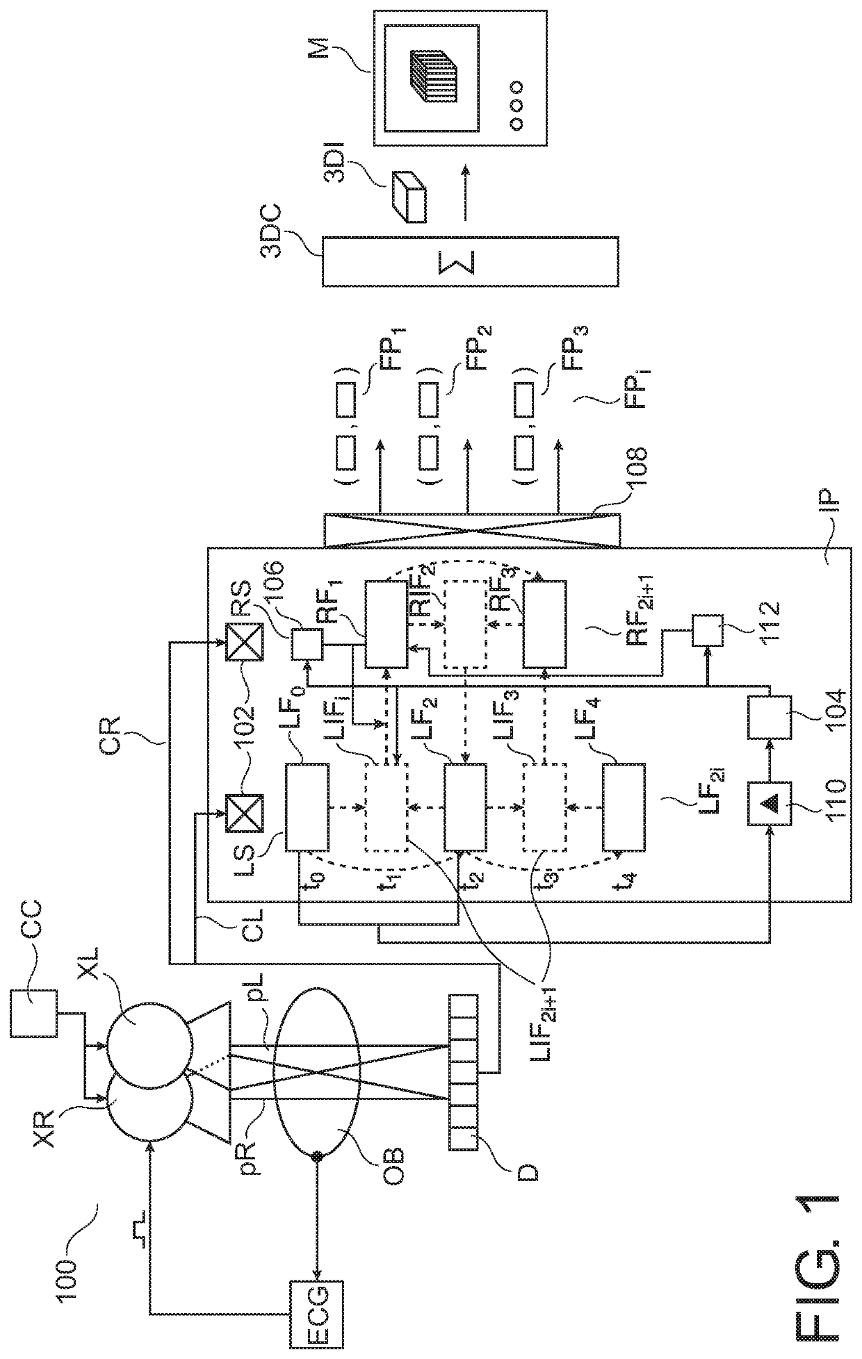
[0034]With reference to FIG. 1, a multi-channel x-ray image processing system (“imager”) 100 is shown.

[0035]In one embodiment the multi-channel imager 100 is a stereoscopic imager with two channels, a right channel CR and a left channel CL. Overall operation of imager 100 is controlled by a computer console CC.

[0036]X-radiation comprising x-ray beams pR, pL are emitted from a right x-ray source XR and a left x-ray source XL, respectively. Only one of X-ray sources XR, XL emits their respective x-rays pR or pL at any one time. X-rays pR or pL are then detected by a single detector D after their respective interaction with an object OB. Alternatively there may be two detectors, one for each x-ray source or tube XL, XR if a bi-plane arrangement is used. The two x-ray tubes XL, XR and the one or more detectors are arranged in a frame (such as a c-arm) or gantry (not shown). According to one embodiment, the frame therefore the position of the x-ray tubes XR, XL and the one or more detect...


PUM


Abstract

An apparatus (IP) and a method to generate temporally-aligned image frames for image-streams (LS, RS) in a multi-channel (CR, CL) imaging system (100). The apparatus (IP) allows reducing or removing temporal distance artifacts that occur when processing the frames into combined image material. The apparatus can also be used to improve signal-to-noise ratio of the frames. The multi-channel imaging system (100) may be a stereoscopic imager.

Description

CROSS-REFERENCE TO PRIOR APPLICATIONS[0001]This application is the U.S. National Phase application under 35 U.S.C. § 371 of International Application Serial No. PCT / IB2013 / 055393, filed on Jul. 1, 2013, which claims the benefit of U.S. Application Ser. No. 61 / 668,046, filed on Jul. 5, 2012. These applications are hereby incorporated by reference herein.FIELD OF THE INVENTION[0002]The present invention relates to image processing apparatuses, to an image processing method, to an image processing system, to a computer program element and to a computer readable medium.BACKGROUND OF THE INVENTION[0003]Multi-channel imaging systems are known in which streams of images (“frames”), one for each channel, are acquired and processed into processed images which may then be displayed on a screen. Examples of such multi-channel imaging systems are stereoscopic systems where frame streams in two channels are produced and then combined into a 3D (three-dimensional) image to provide for example an ...

Claims


Application Information

Patent Timeline
Patent Type & Authority Patents(United States)
IPC IPC(8): H04N5/04H04N13/00H04N13/161A61B6/00A61B6/02G06T11/00G06T7/38
CPCH04N5/04A61B6/022A61B6/4007A61B6/5229G06T7/38G06T11/005H04N13/161A61B6/466G06T2207/10021G06T2207/10116G06T2211/464
Inventor STEINHAUSER, HEIDRUNADMIRAAL, ALEXANDER JOHANNESDE PAUS, ROBIN PIETERDEN HARTOG, MARKUS JOHANNES HARMENKREMER, FRANS HENK
Owner KONINKLJIJKE PHILIPS NV
Features
  • R&D
  • Intellectual Property
  • Life Sciences
  • Materials
  • Tech Scout
  • Unparalleled Data Quality
  • Higher Quality Content
  • 60% Fewer Hallucinations
Learn More